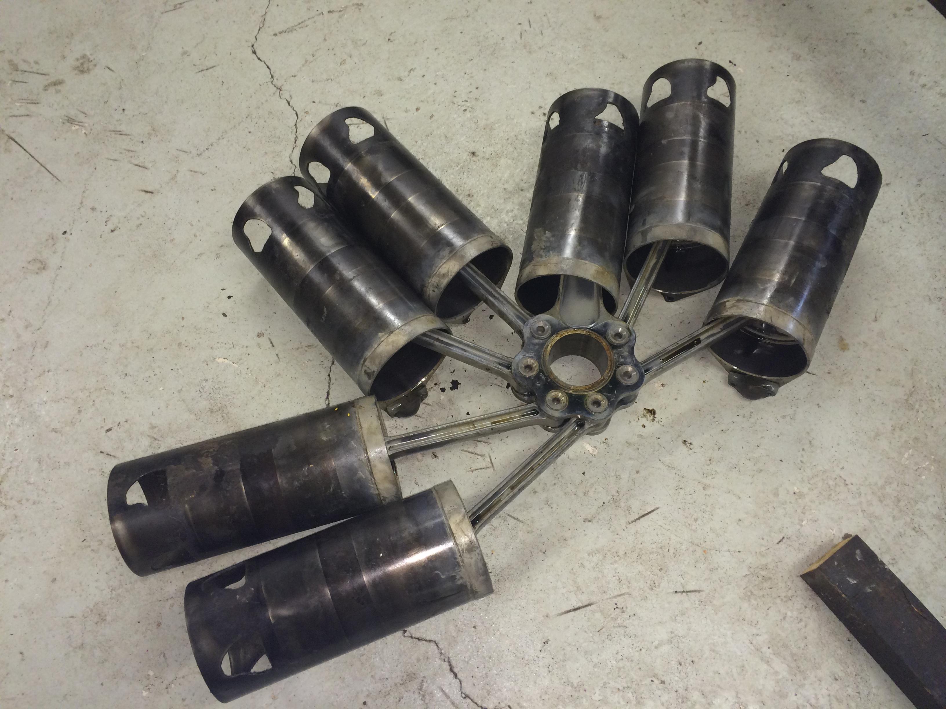
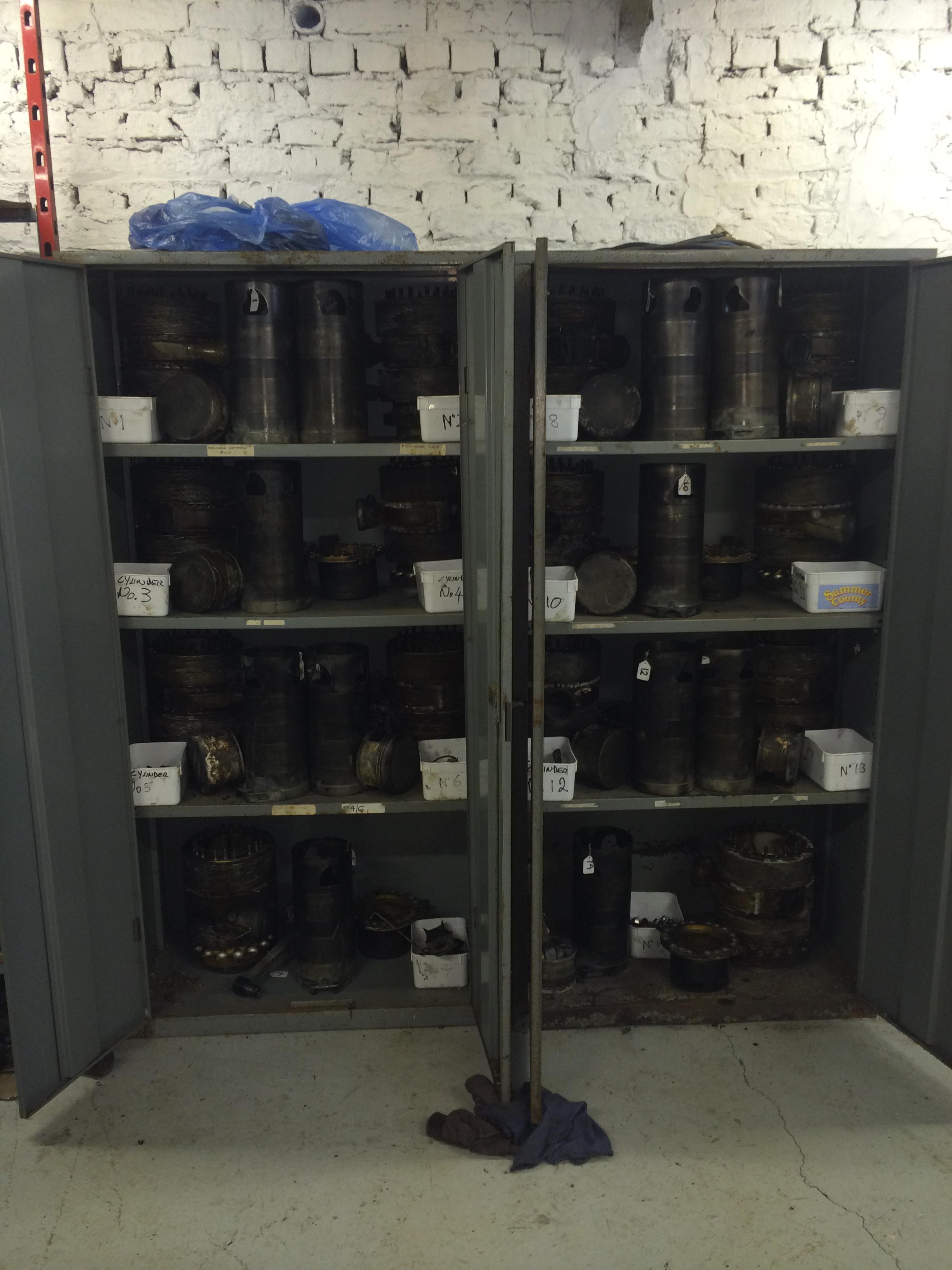
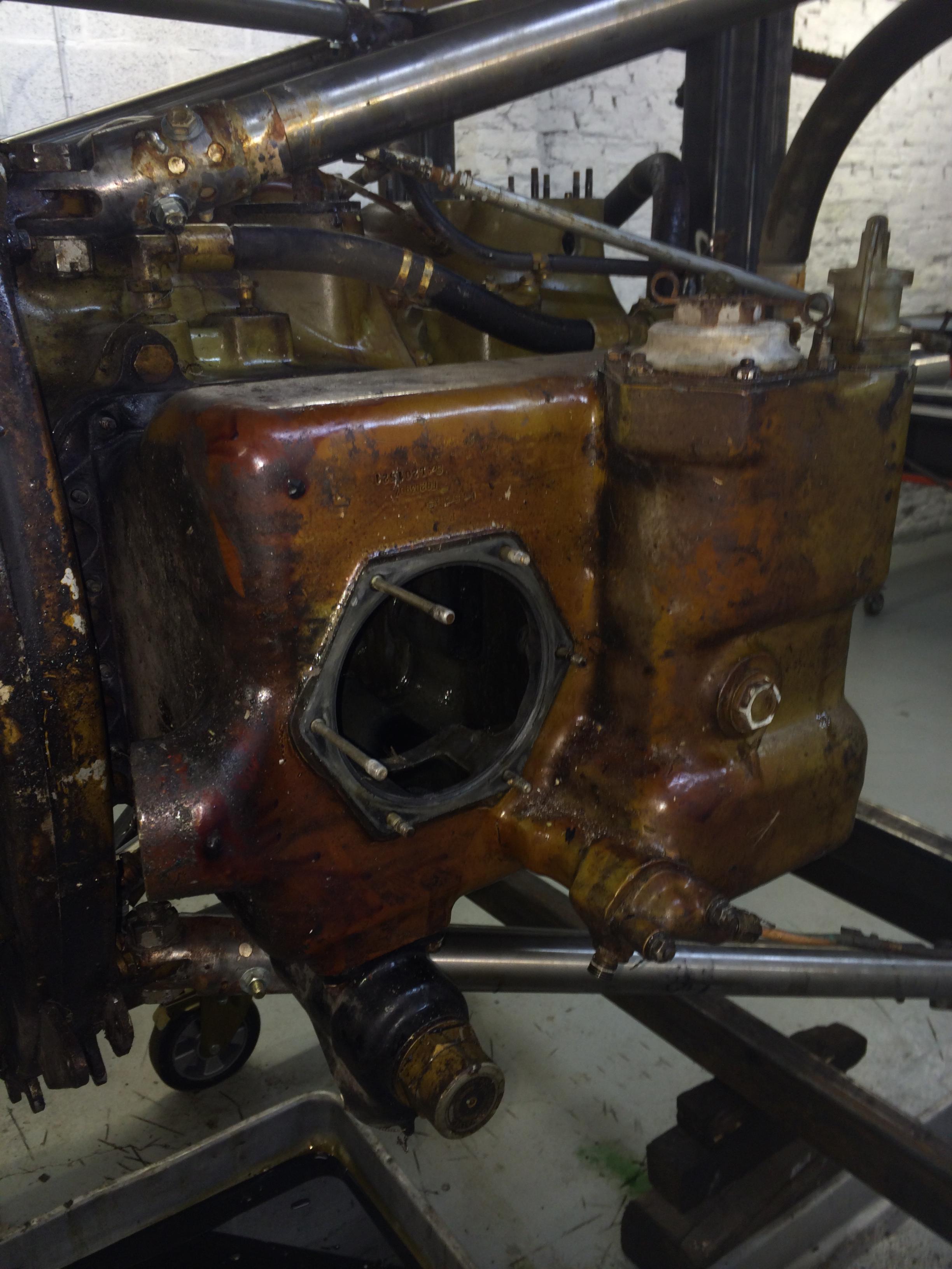
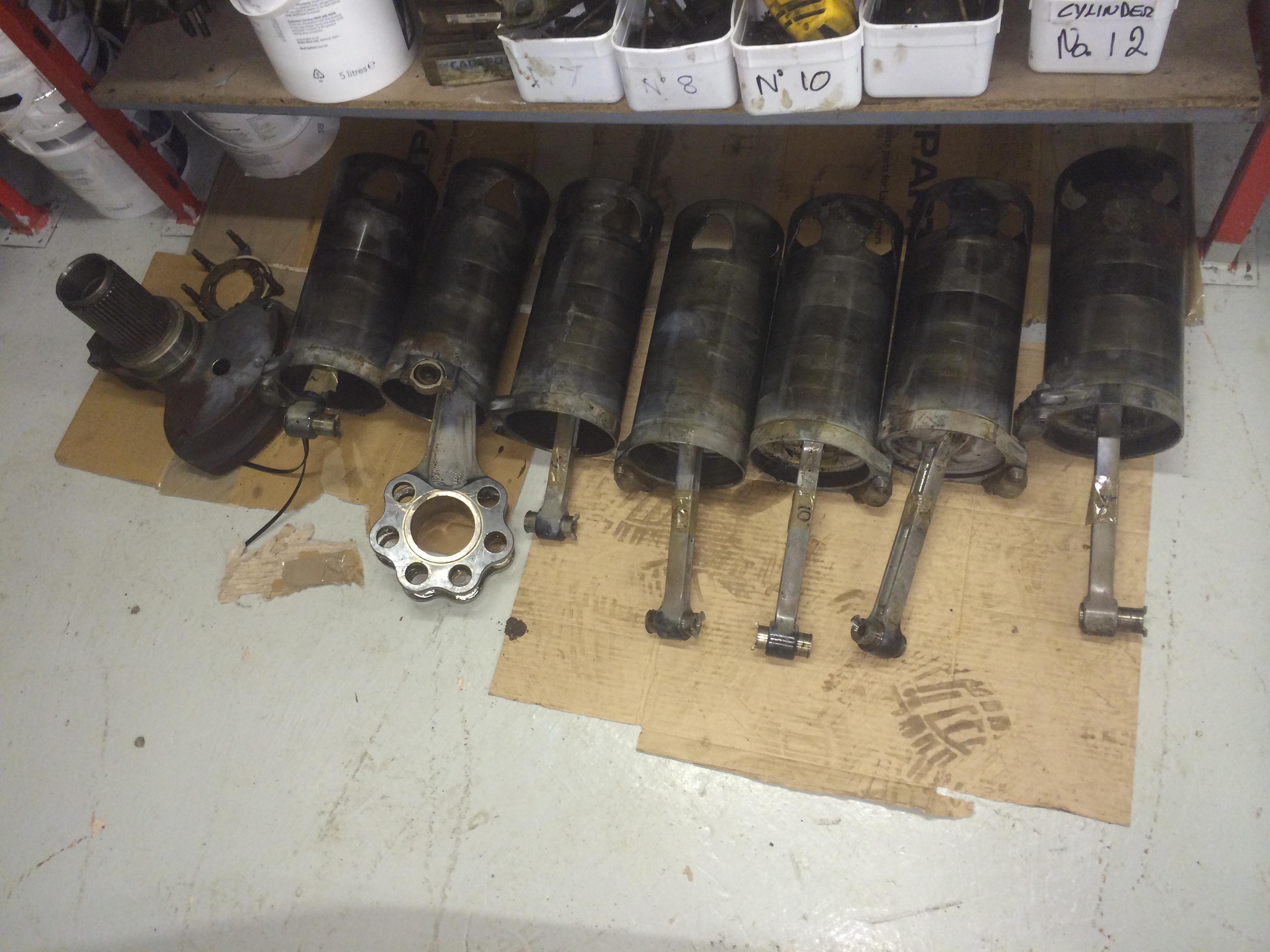
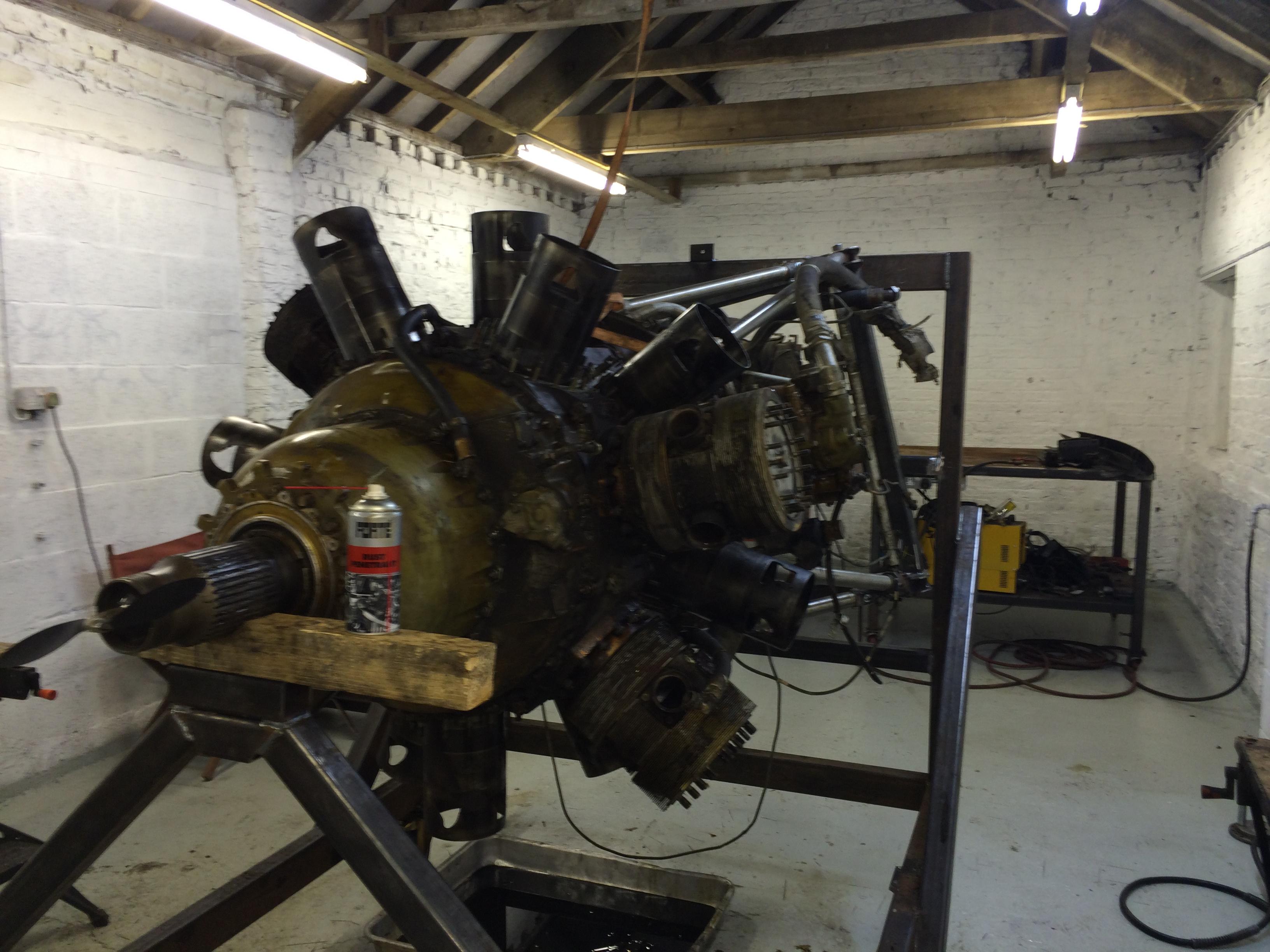
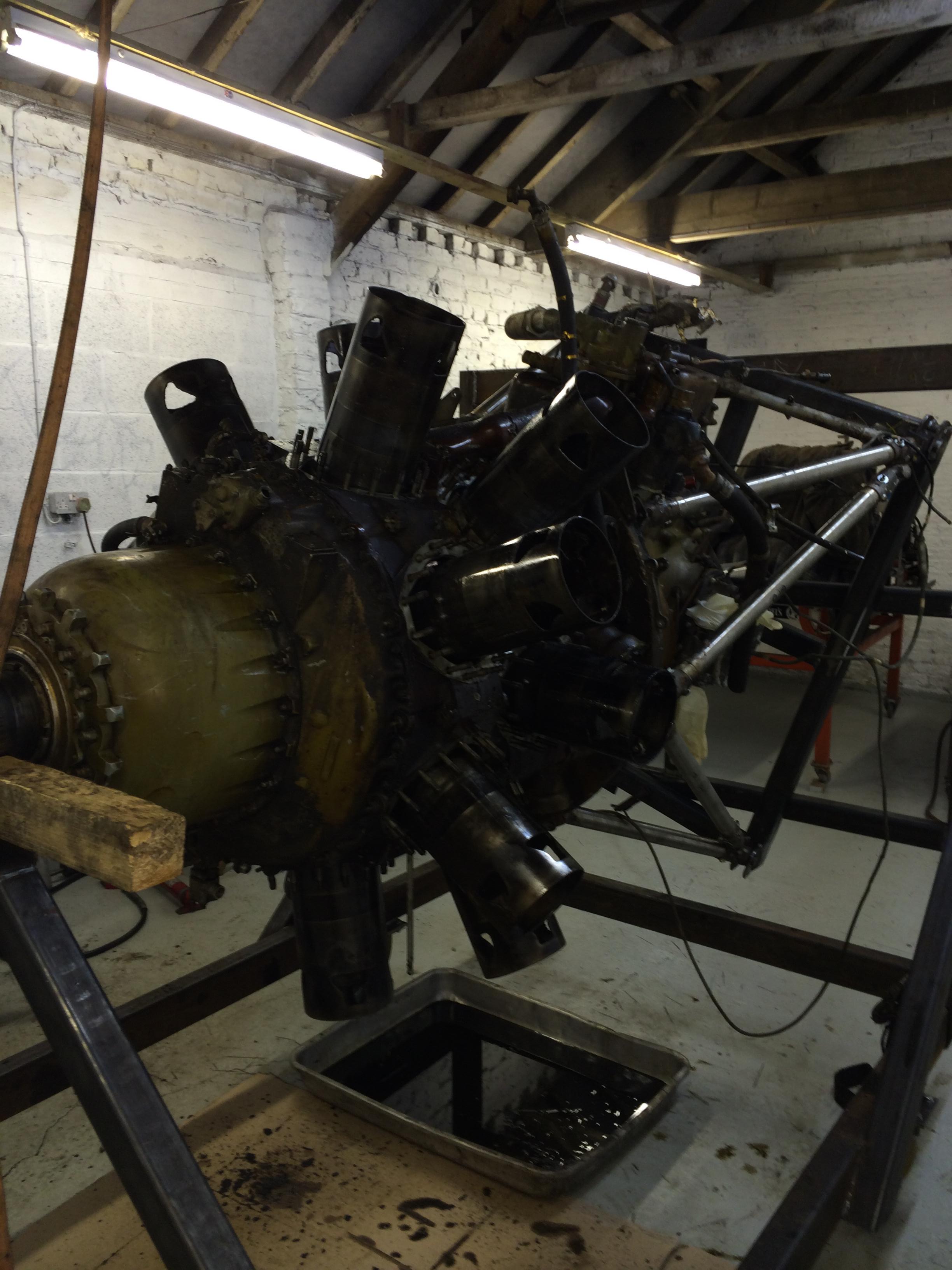
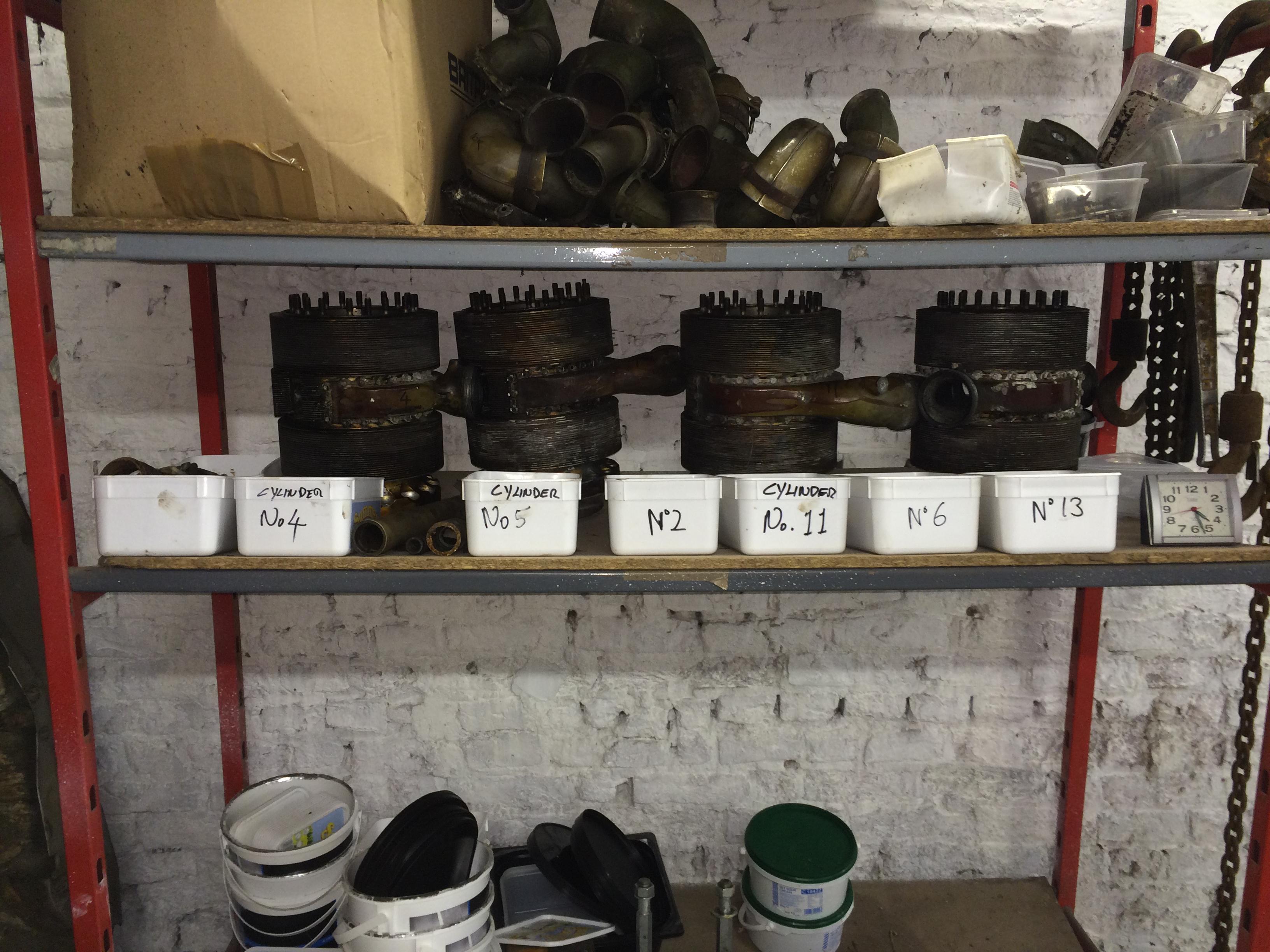
One of the reasons we have to dismantle the crank case is, we need to remove the sleeves, pistons and con rods as one unit, as the pistons are stuck in the sleeves. The condition of the sleeves below the pistons is in very good condition so they should push out with little effort.
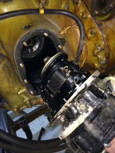
Removing the magnetos was straight forward
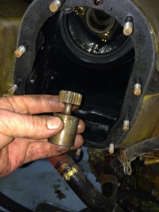
Also remove the coupling shaft
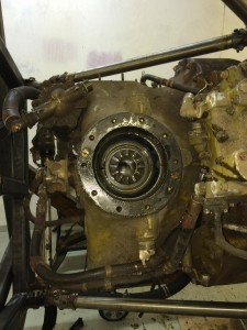
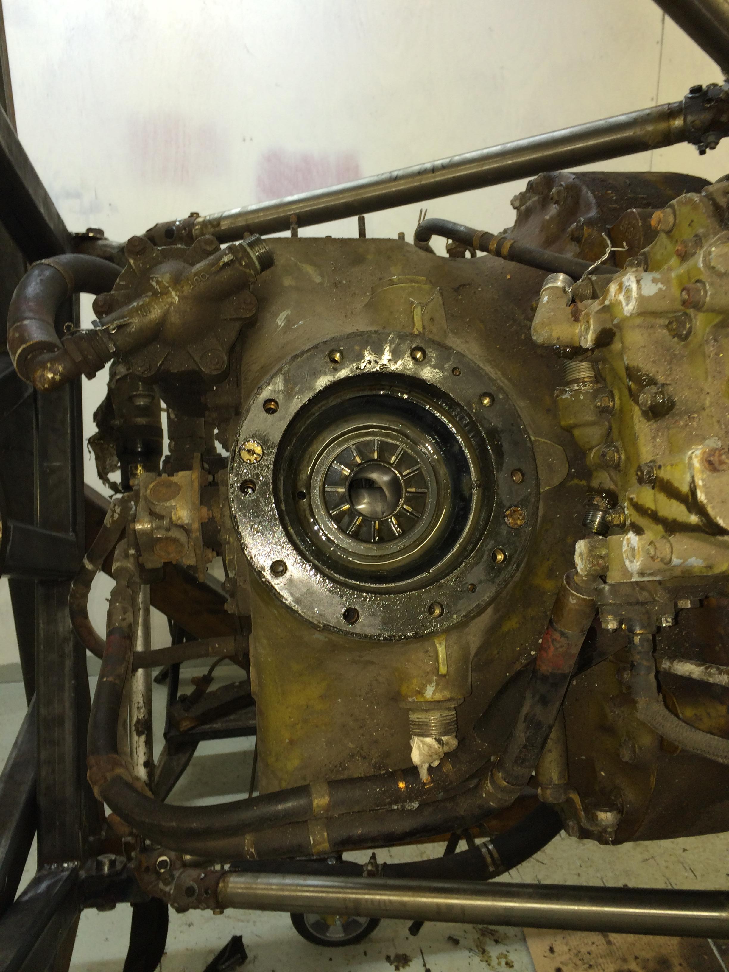
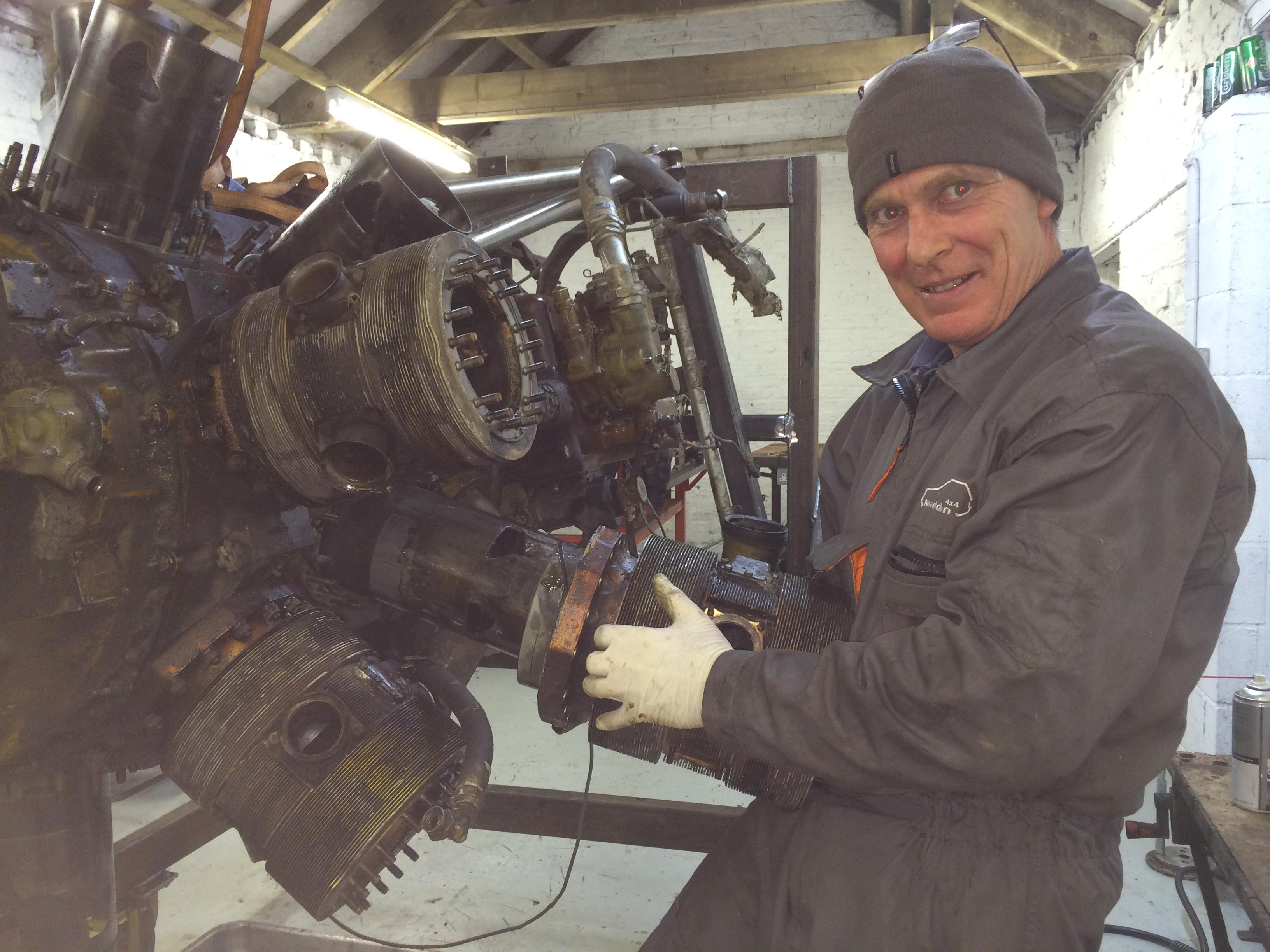
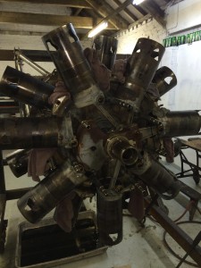
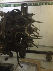
Starter removed, as you can see the internals of the engine is in very good condition.

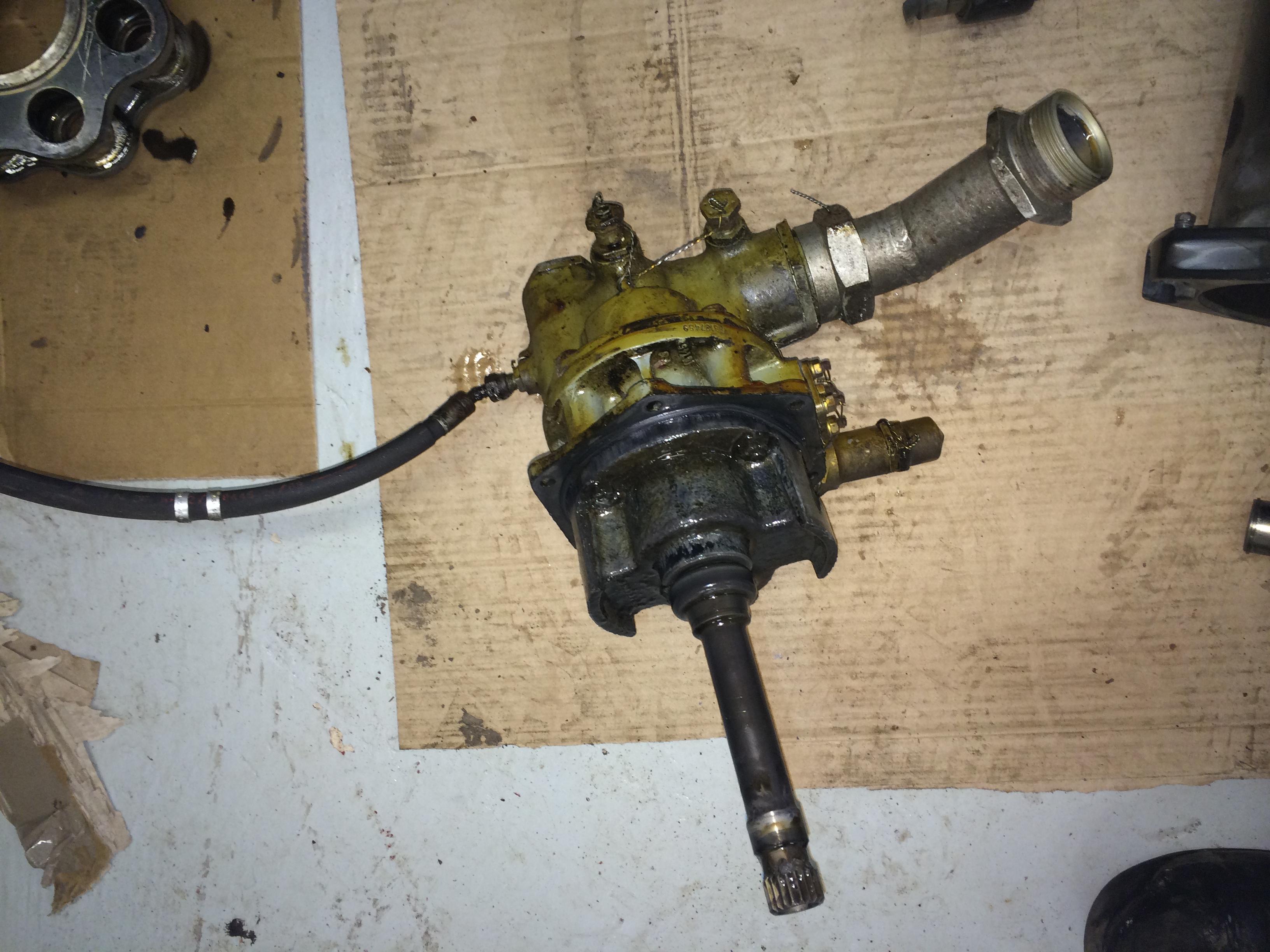
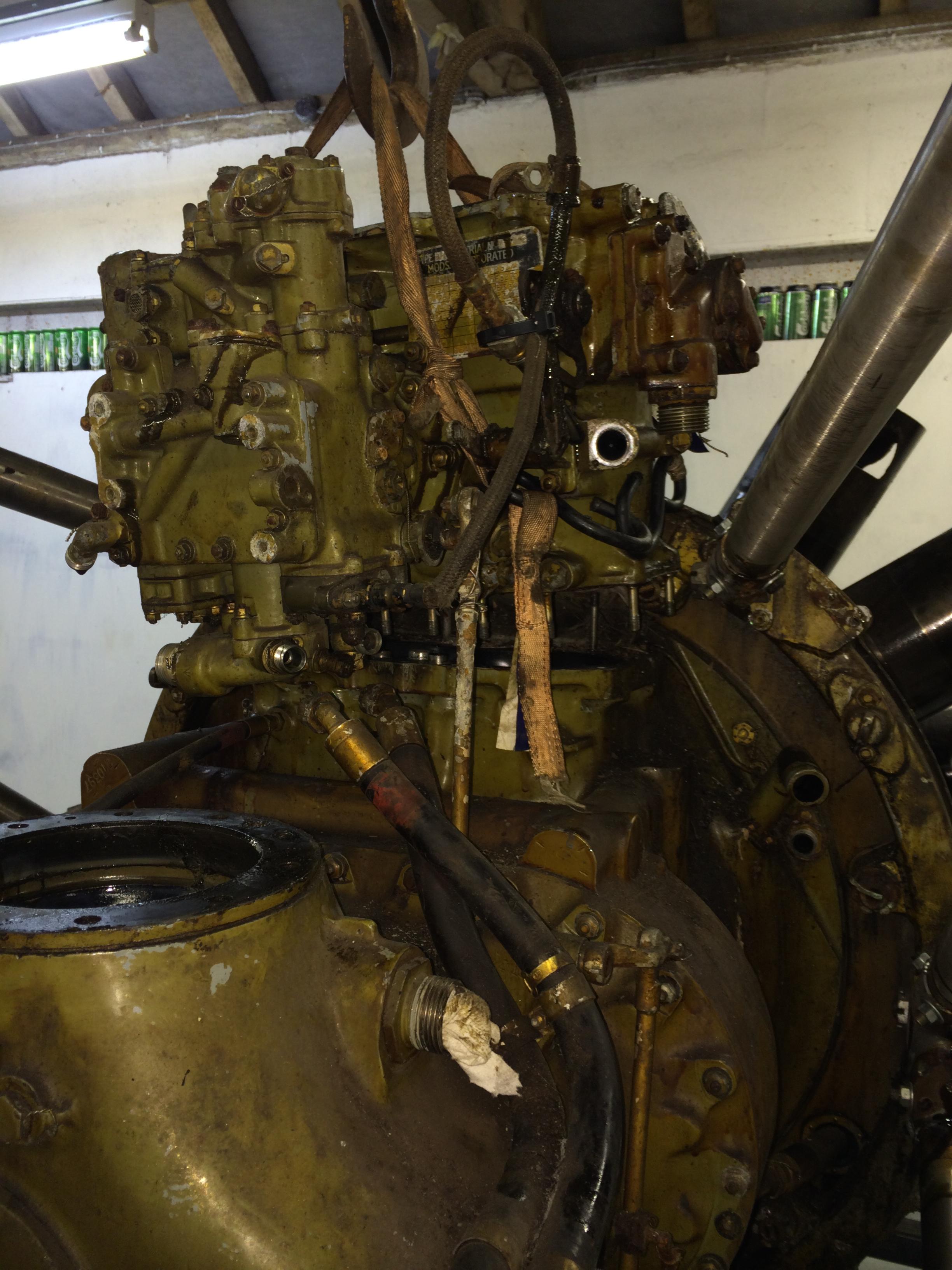
Next job was to remove the Hobson Injection System. As Pete was away driving a A340-600 to Sydney and back I used the third member of the team to assist , Mr Engine Hoist.
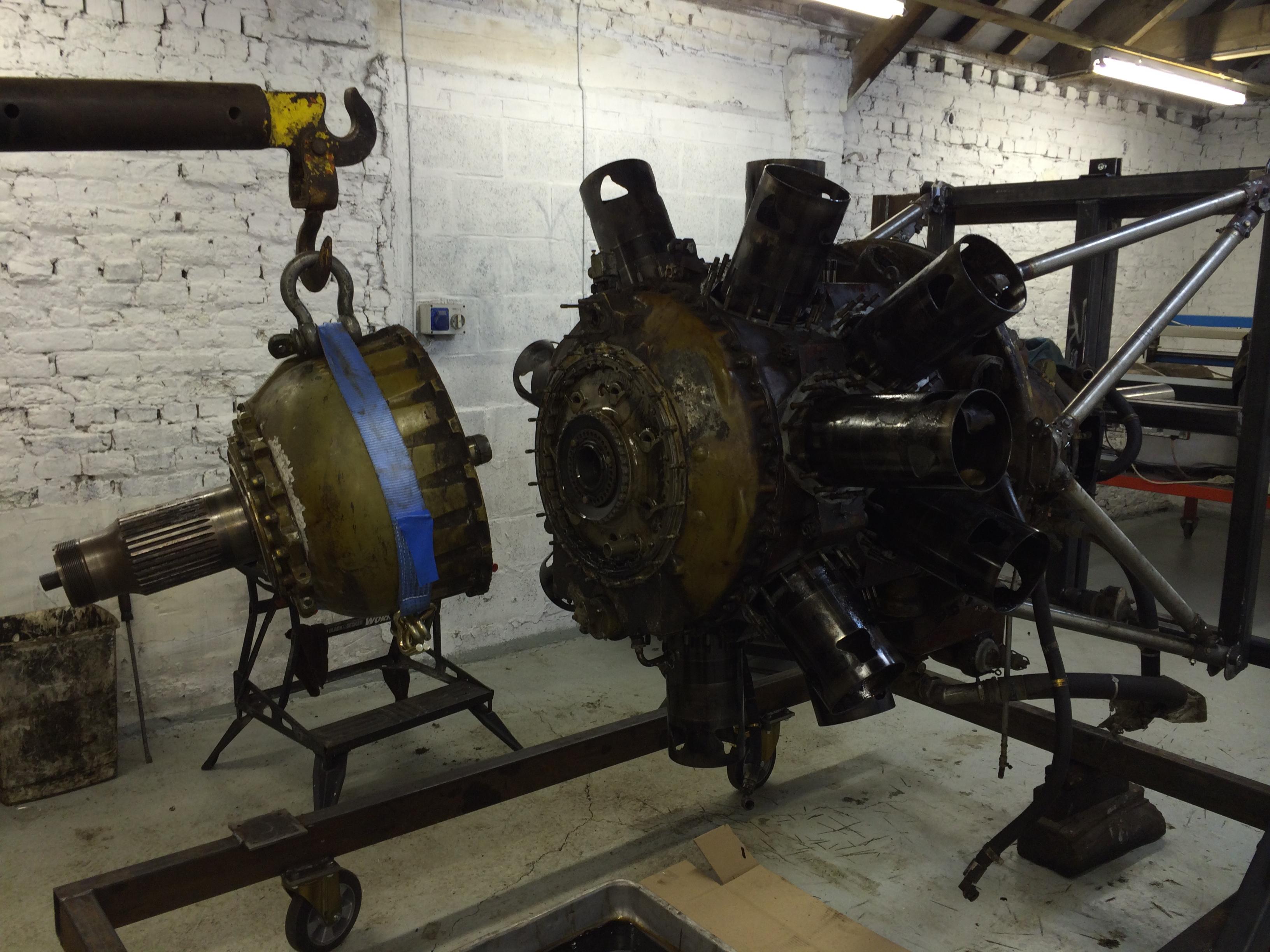
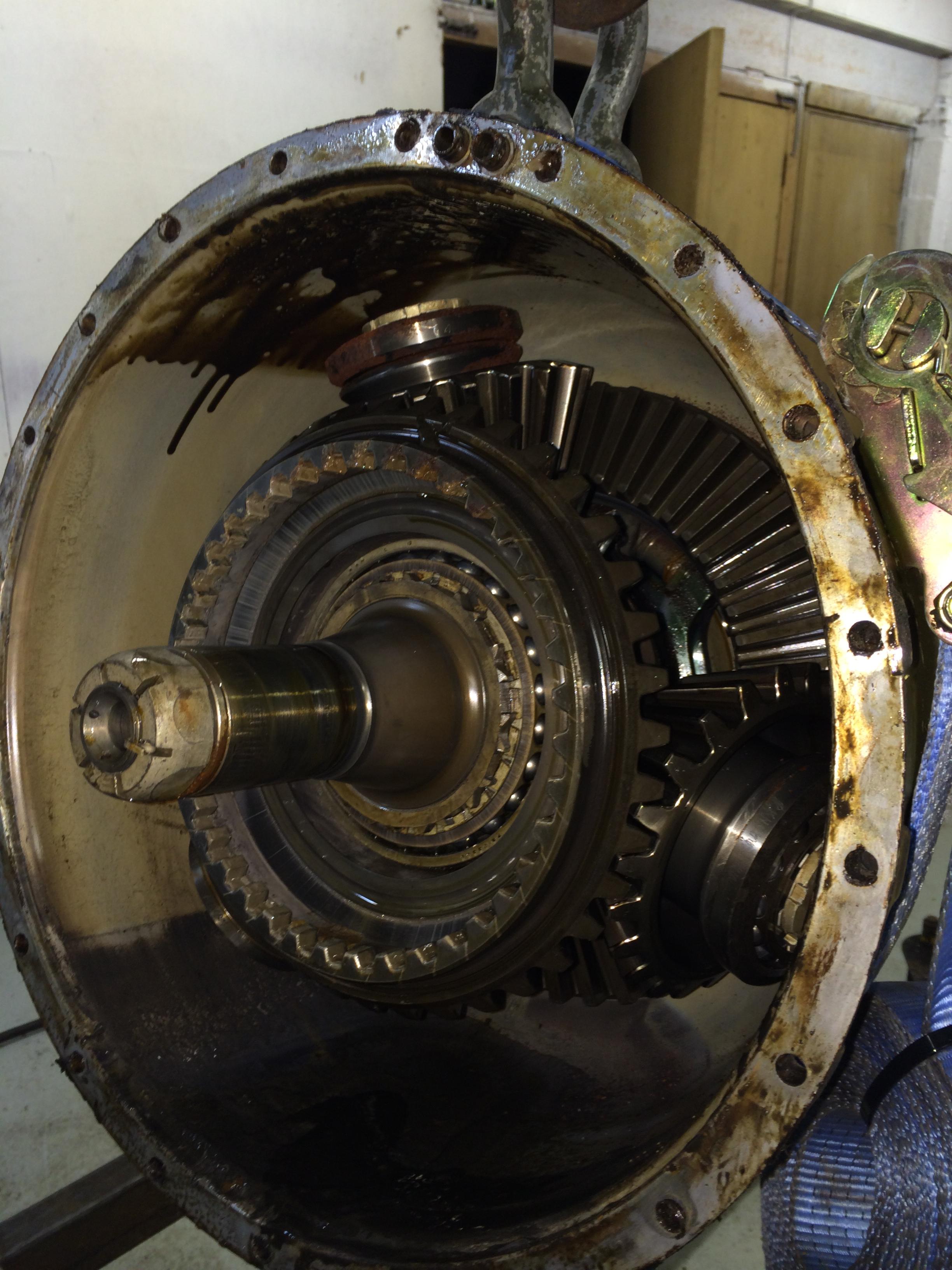
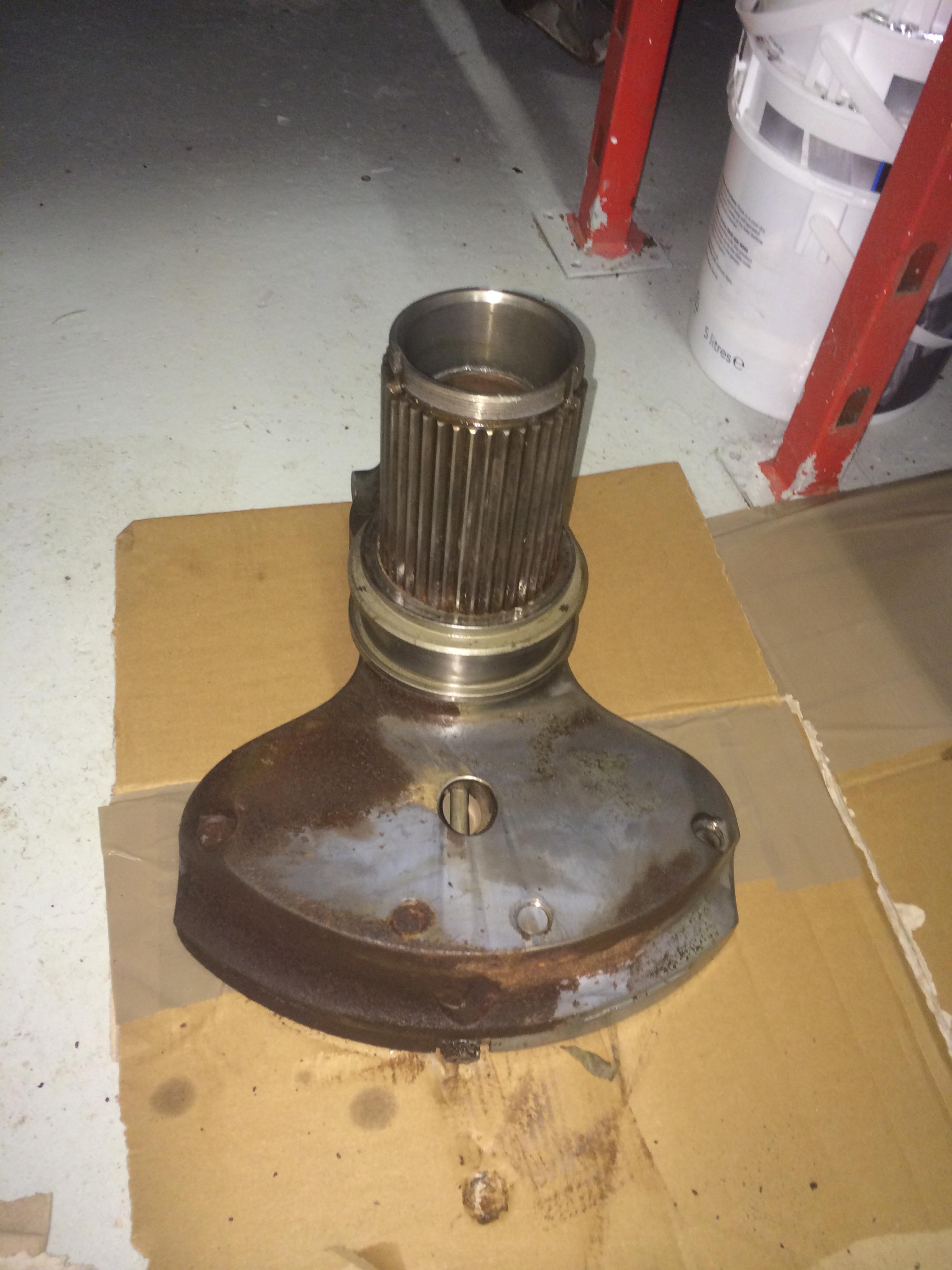
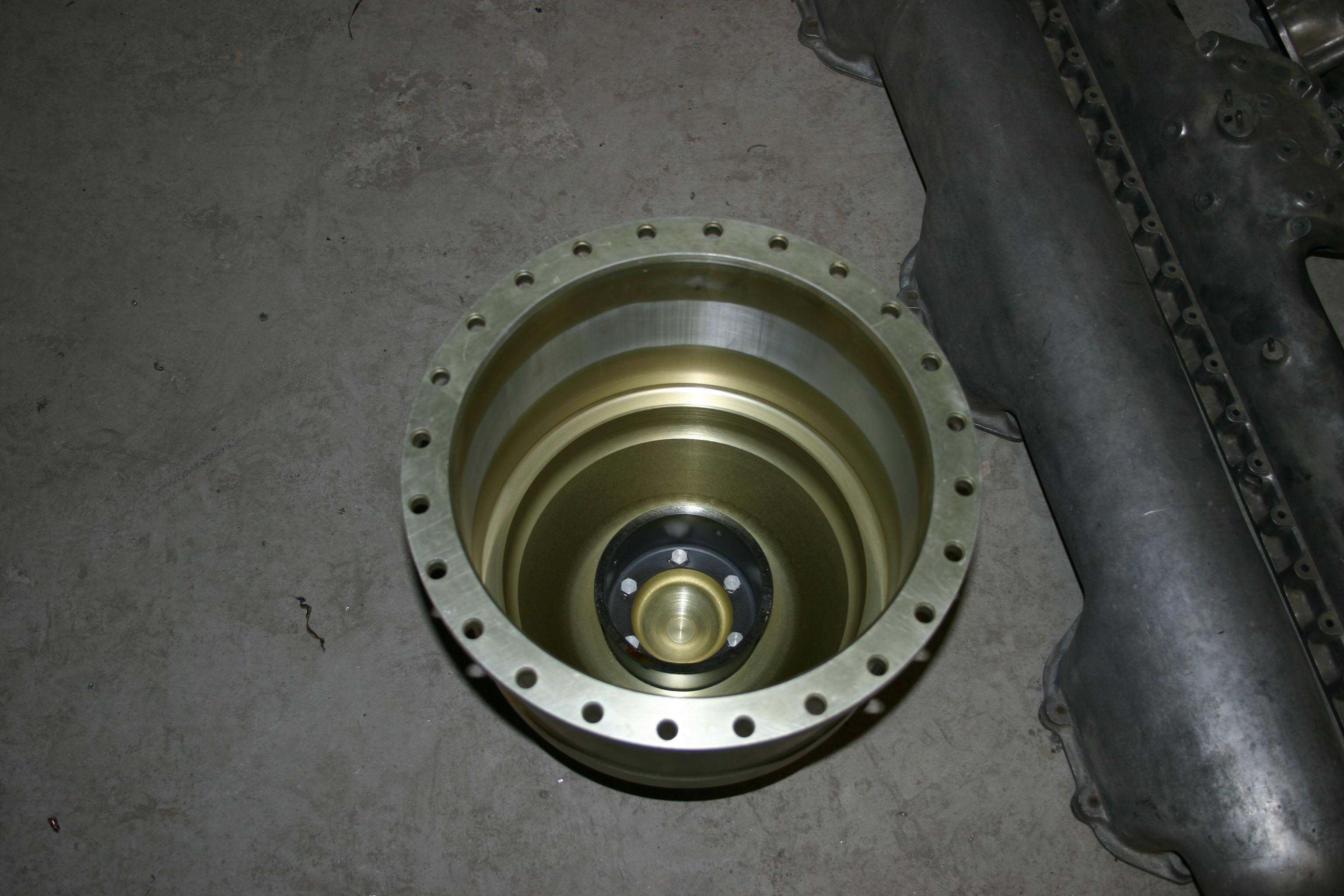
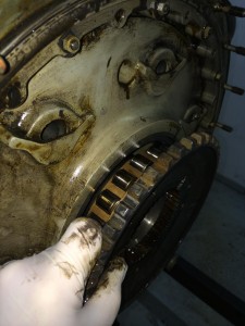
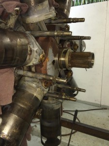
Next job was to remove the reduction gear, as per the manual a little tap with a hide hammer and it came off.

The condition of the reduction gear is excellent , and turns freely for the first time in thirty five years or so.

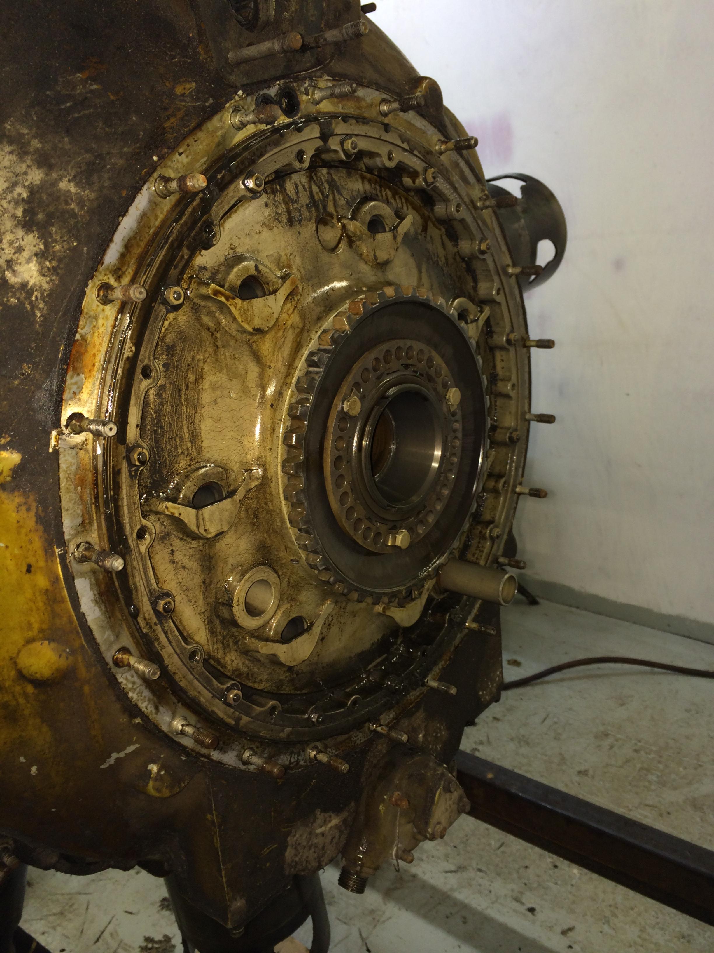
Next to come off was the reduction gear drive gear.
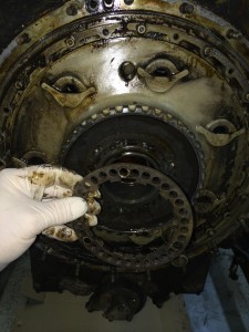
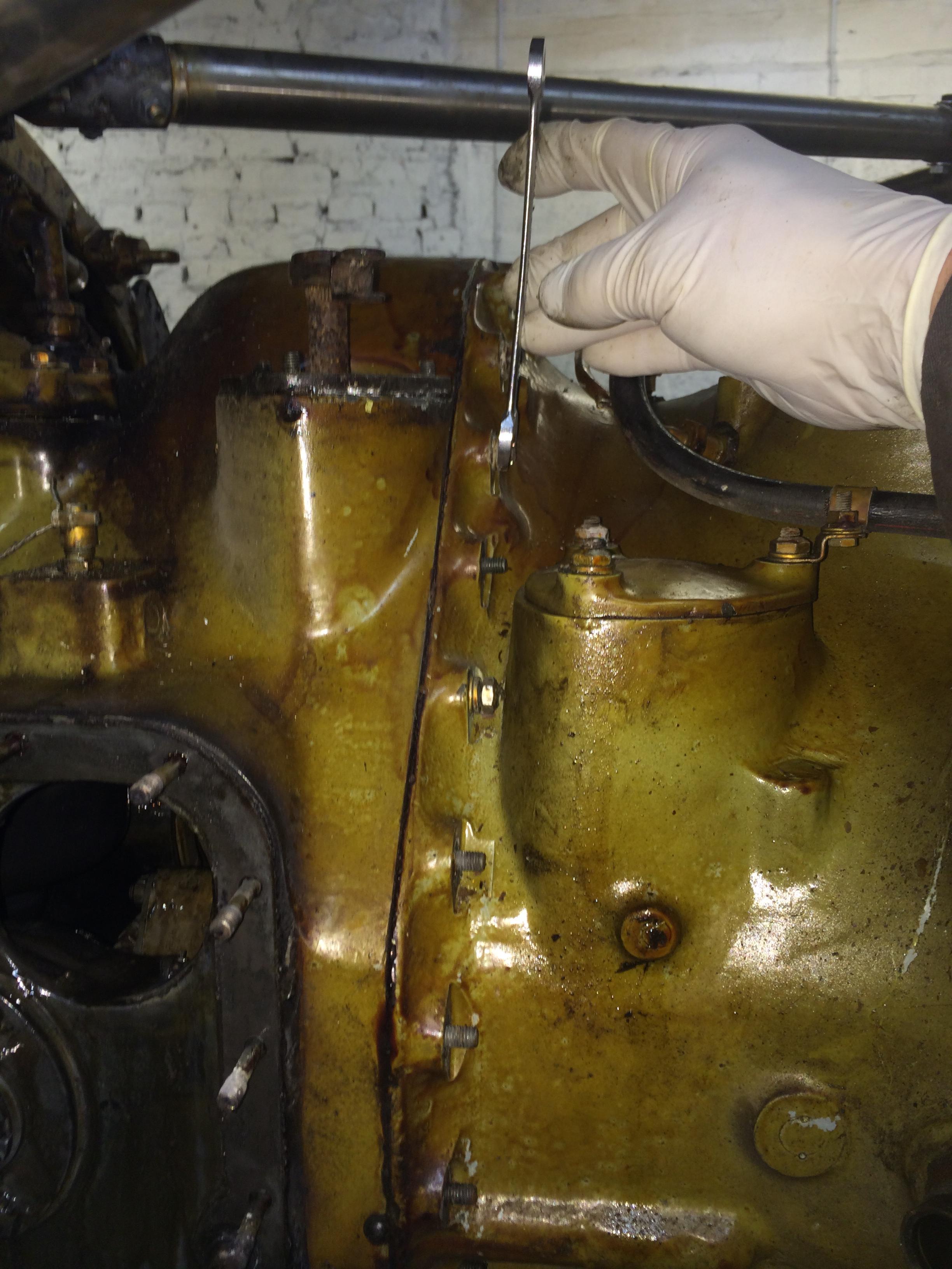
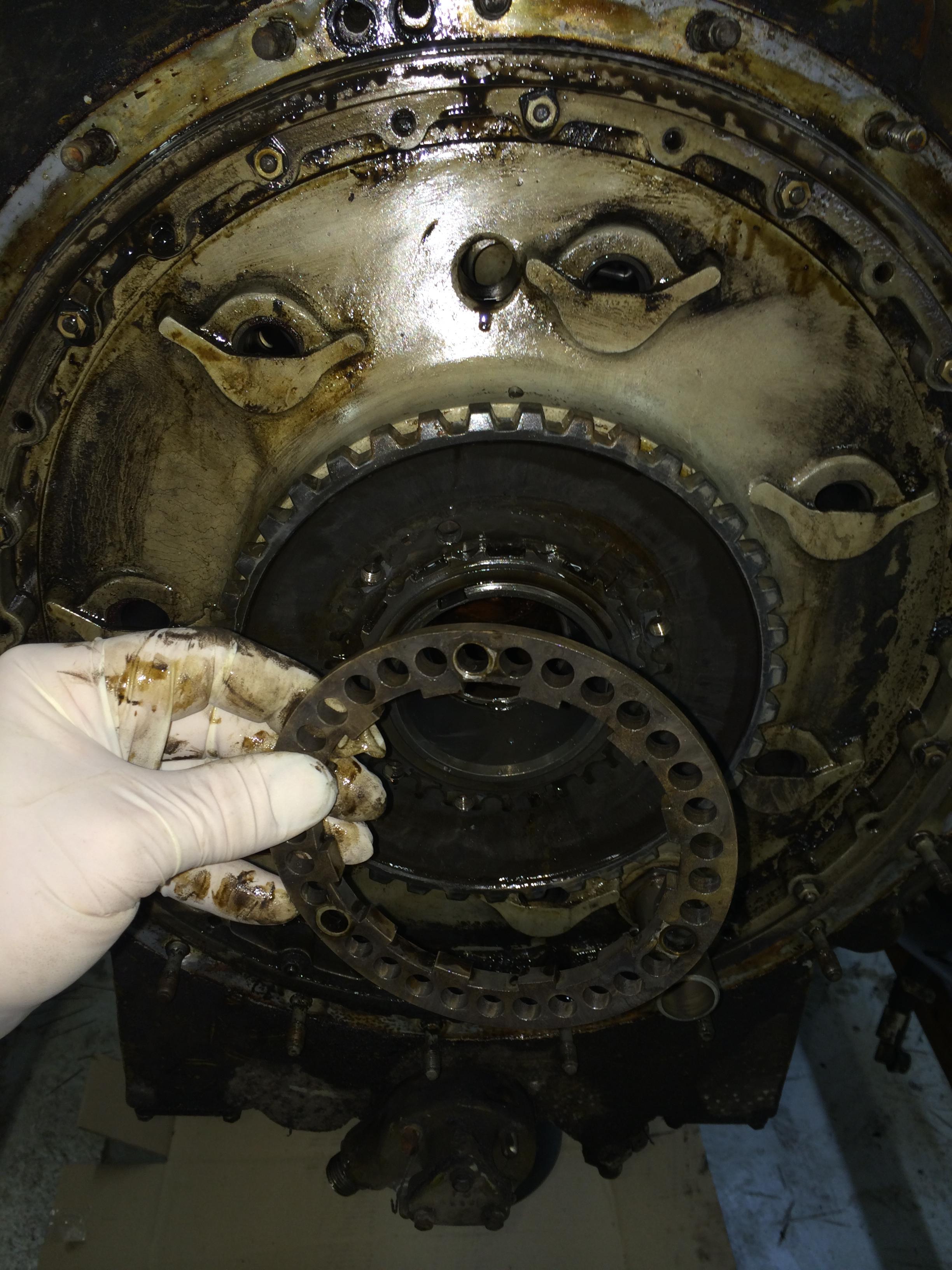
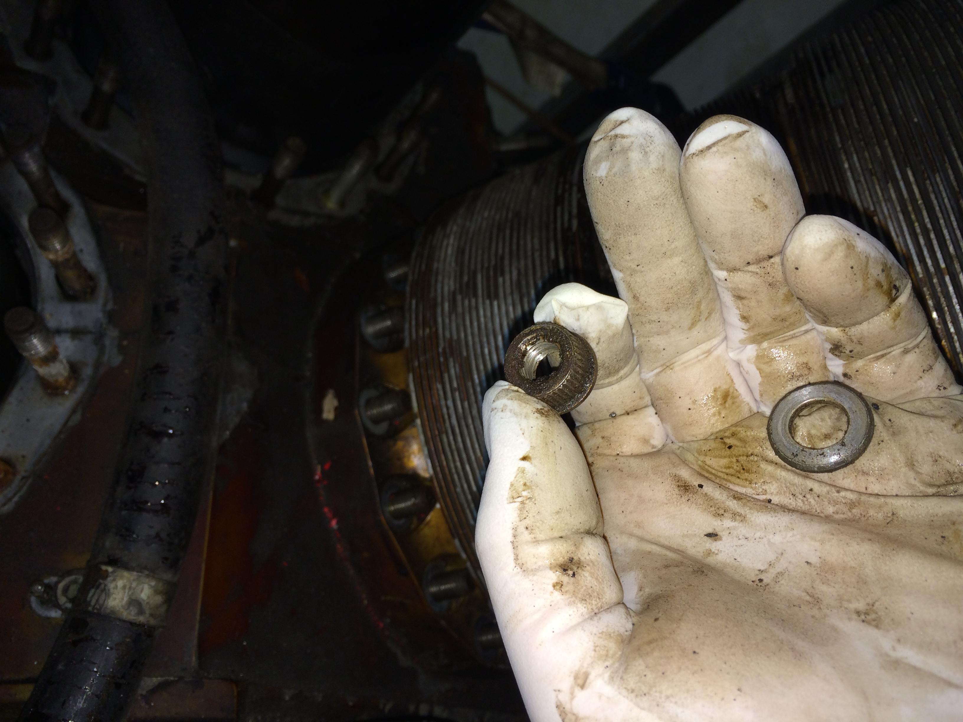
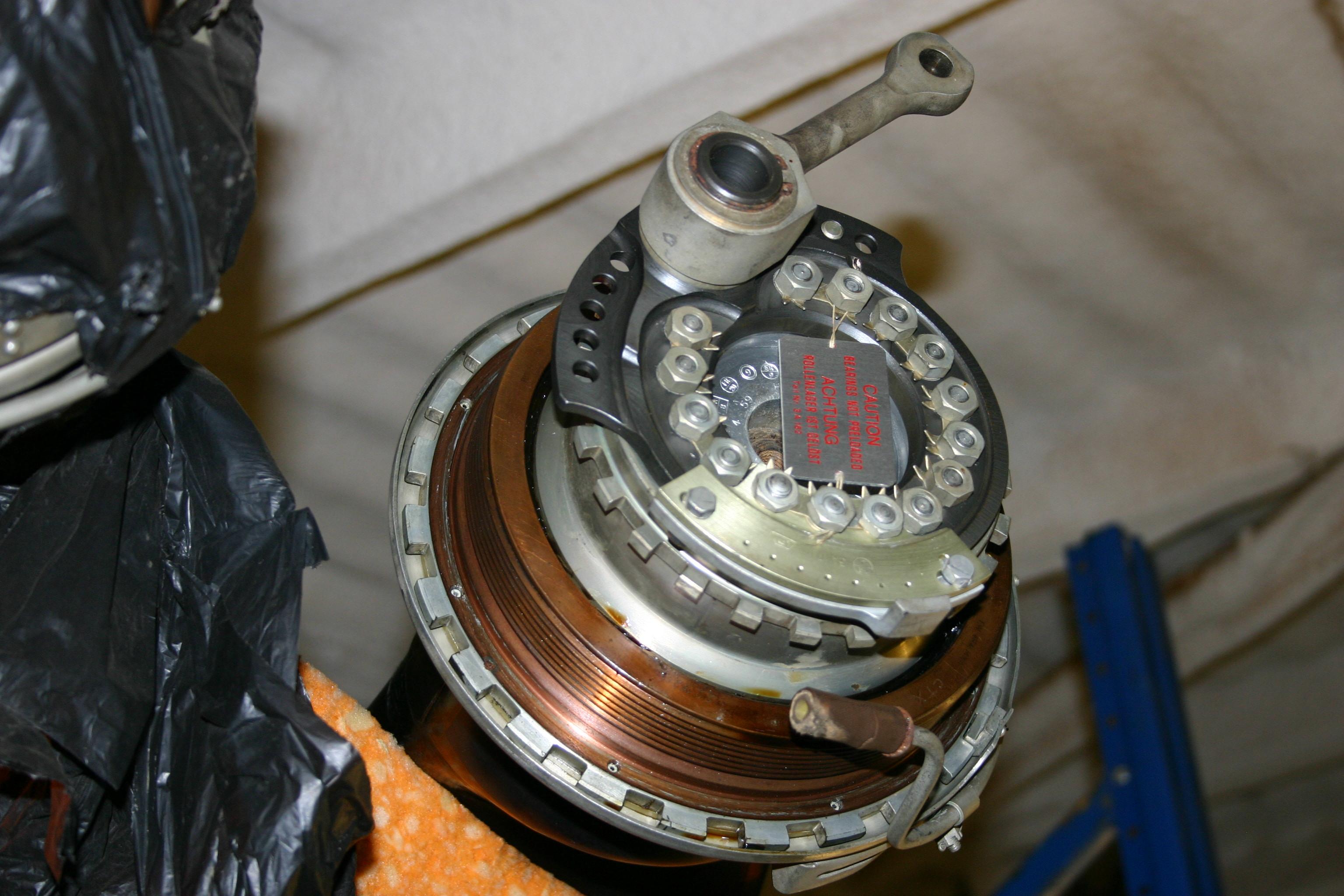
Take off the locking ring.

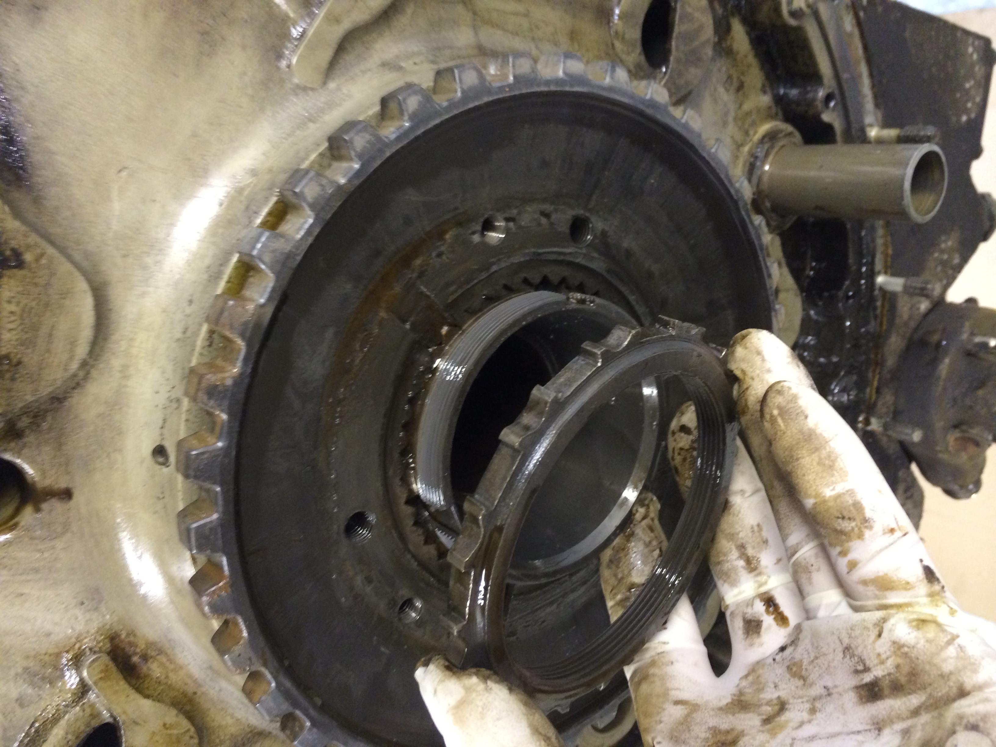
Then take of the left hand threaded lock nut (good job I read the manual!) then remove the gear with the inner race of the front cover.
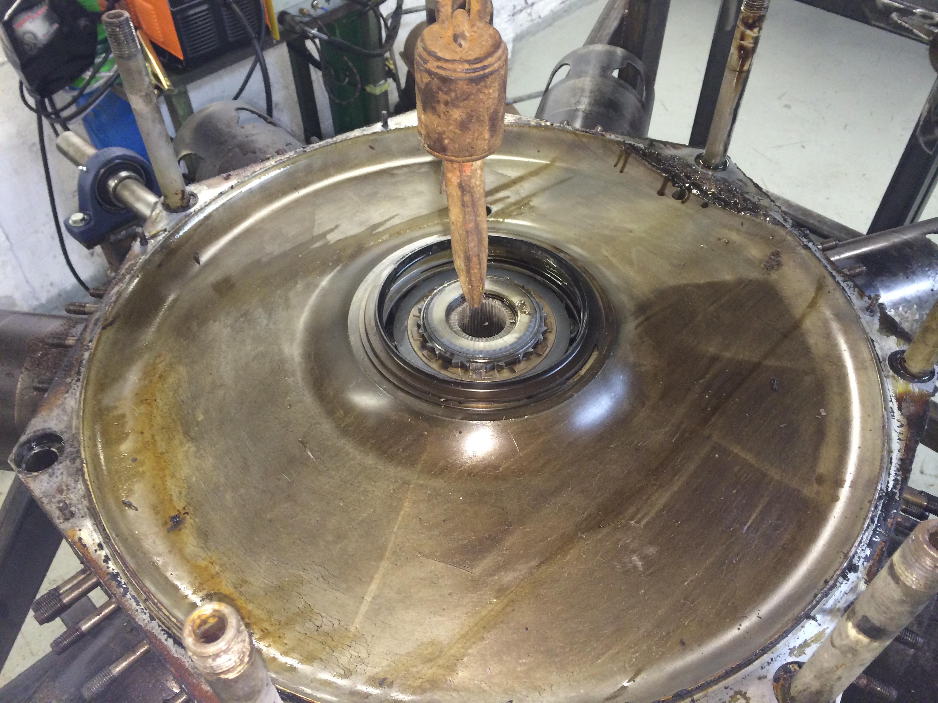
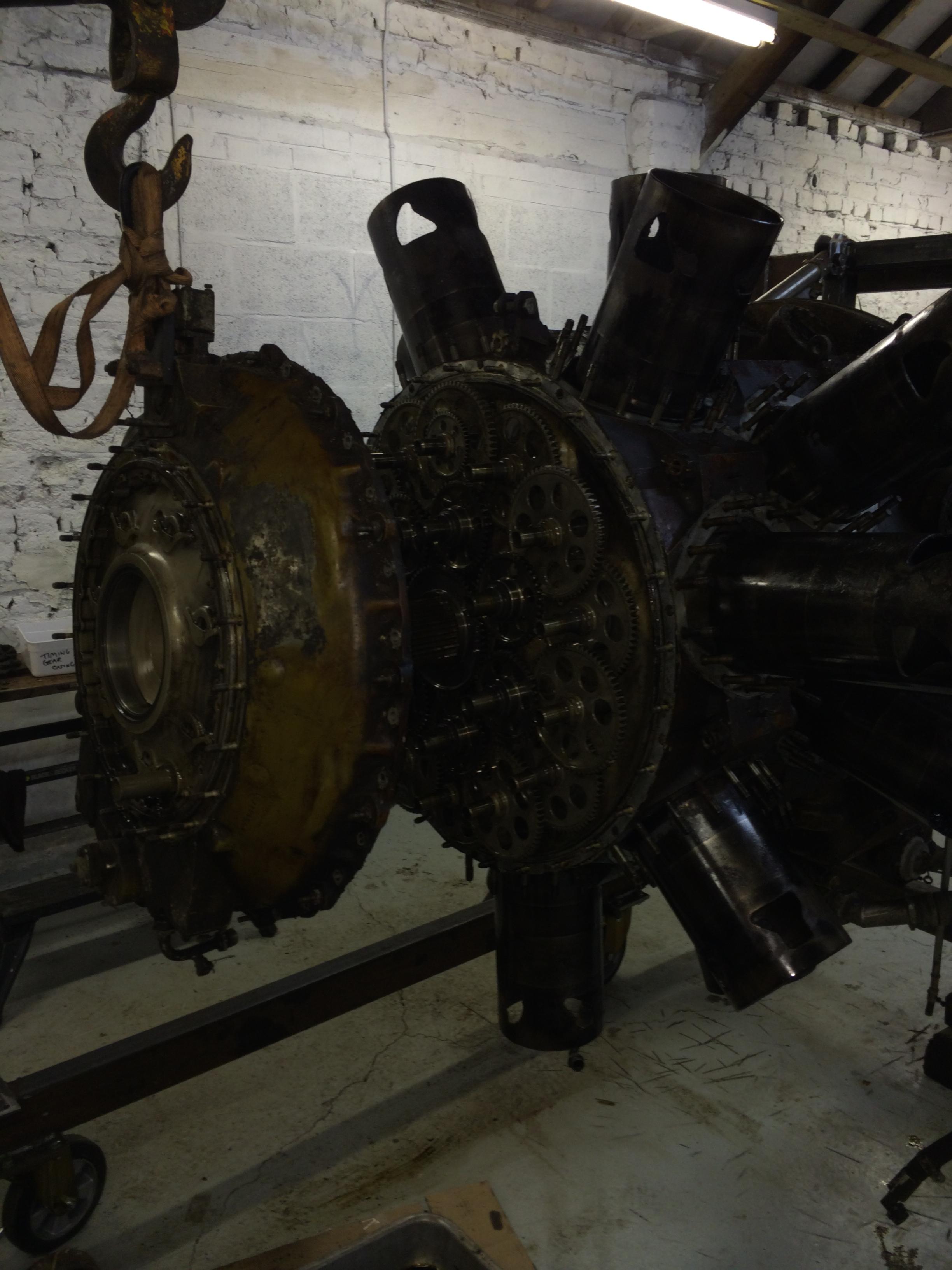
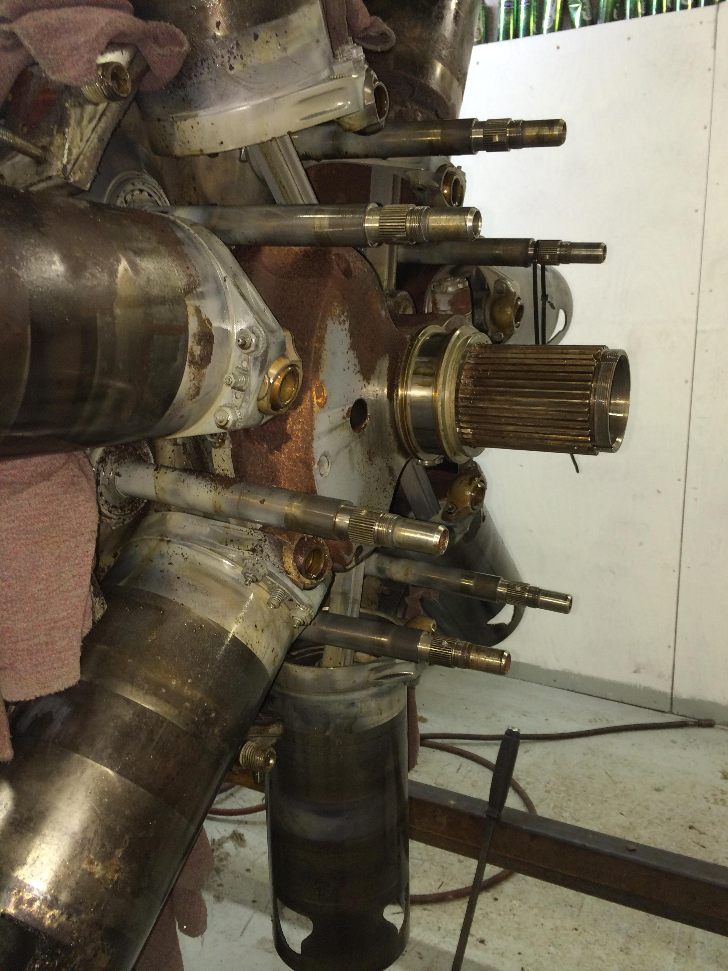
Next we will remove the front cover to reveal the wonders of the Bristol Hercules engine, the timing gears.

And in we go! Pete spent a good day in the workshop and stripped down the timing cover and gears.
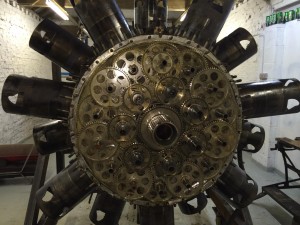
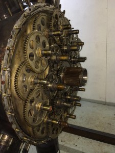
The wonders of a Bristol Hercules, you can not stop admiring the mass of timing gears but in fact it is quite simple.
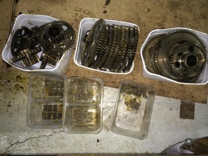
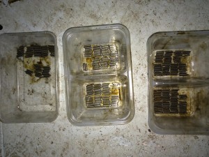
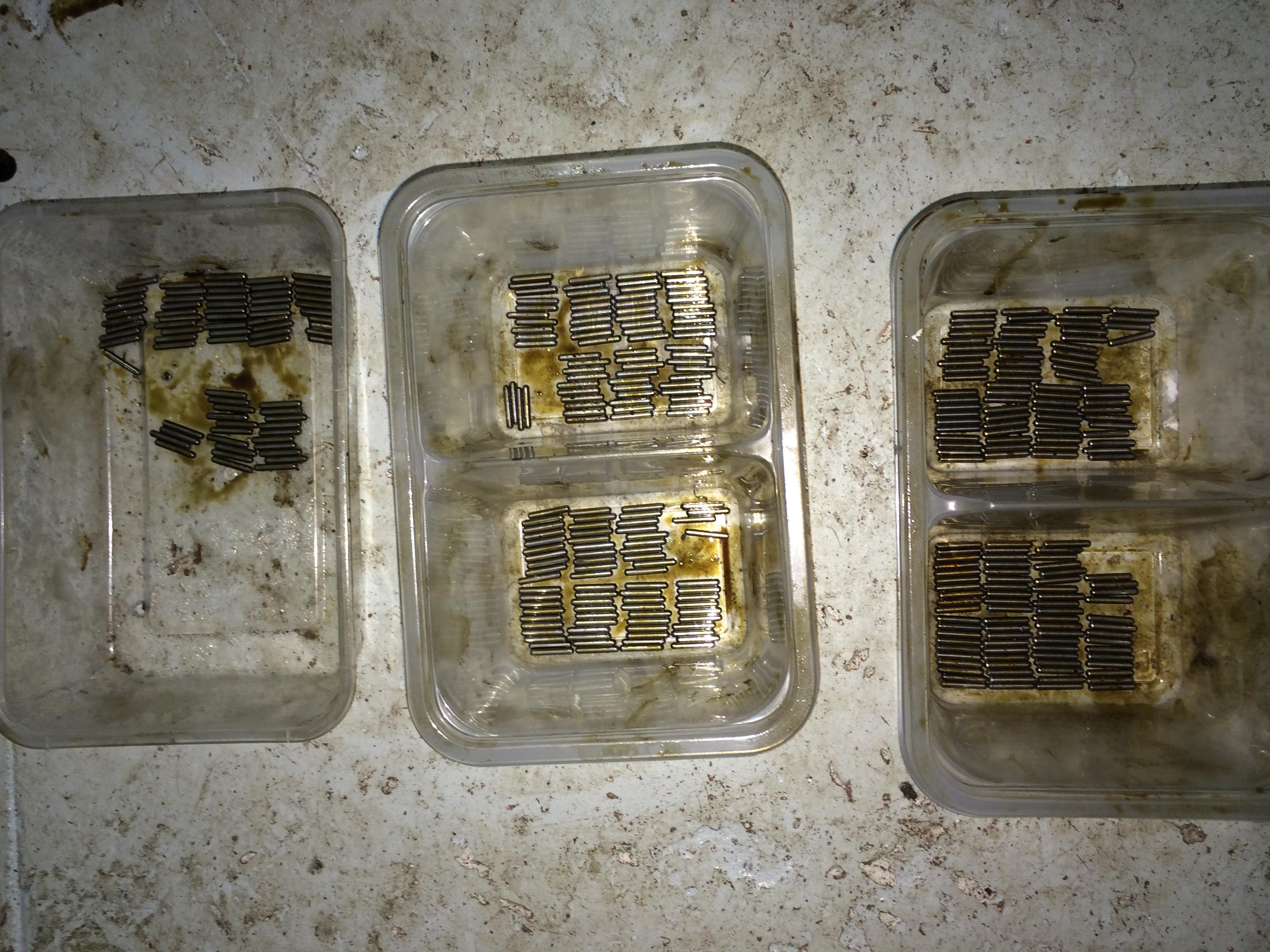
Next job was to strip down the gears. It says in the manual “Provide provision to catch the 74 needle rollers from each transfer gear” that is an under statement! as Pete found out! But they are all accounted for.

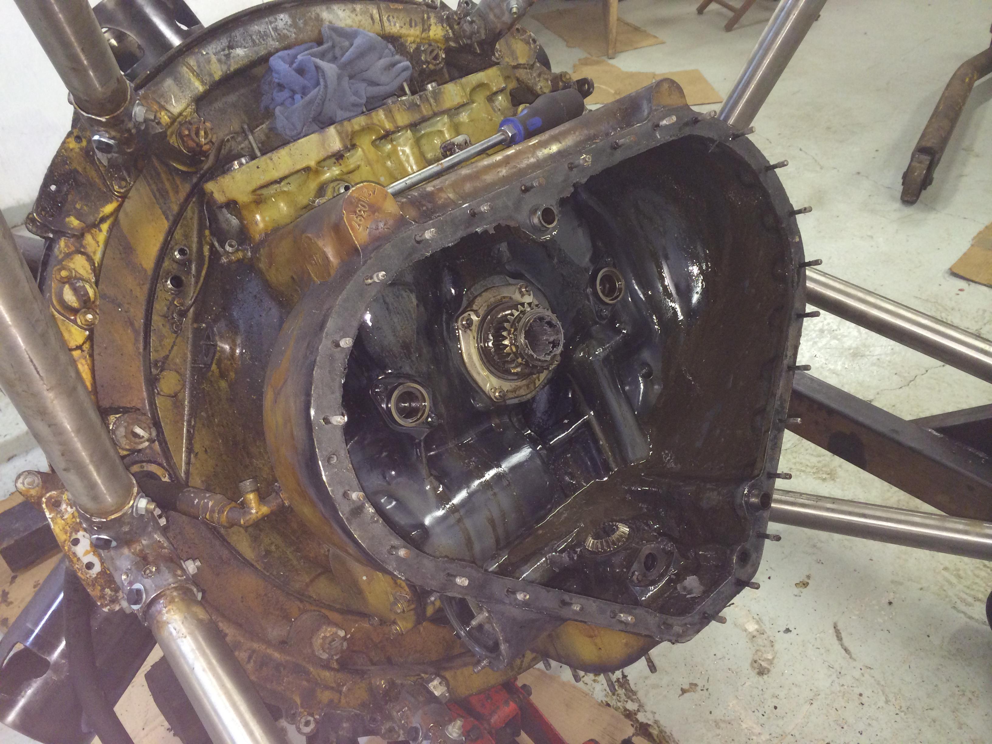
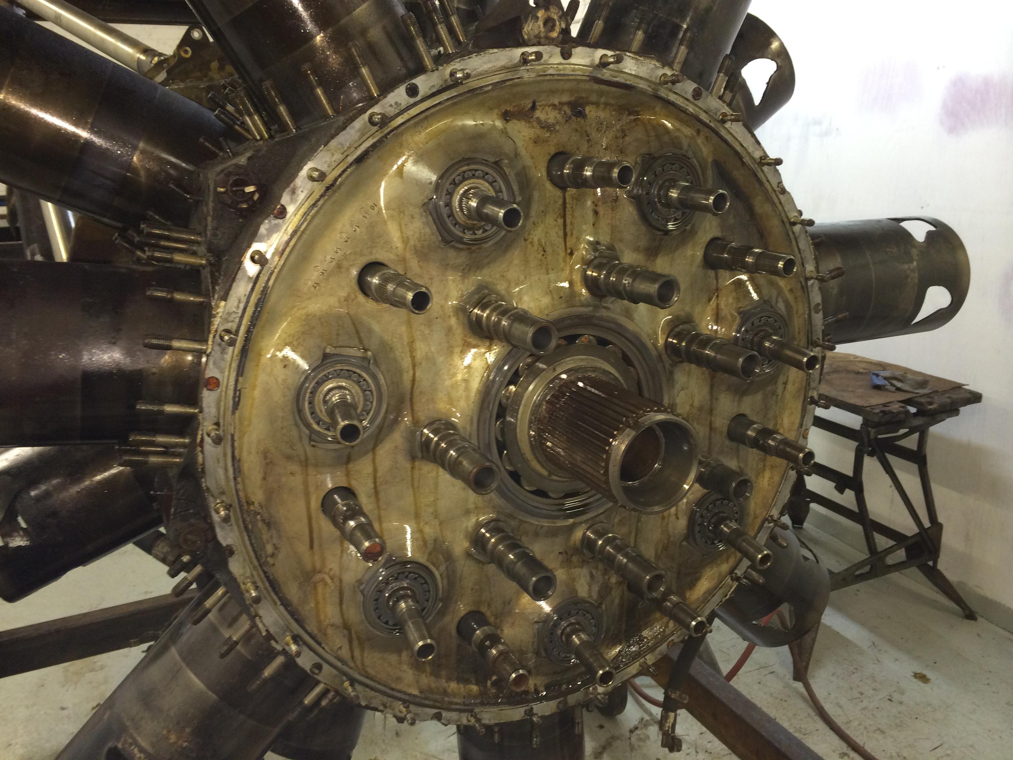
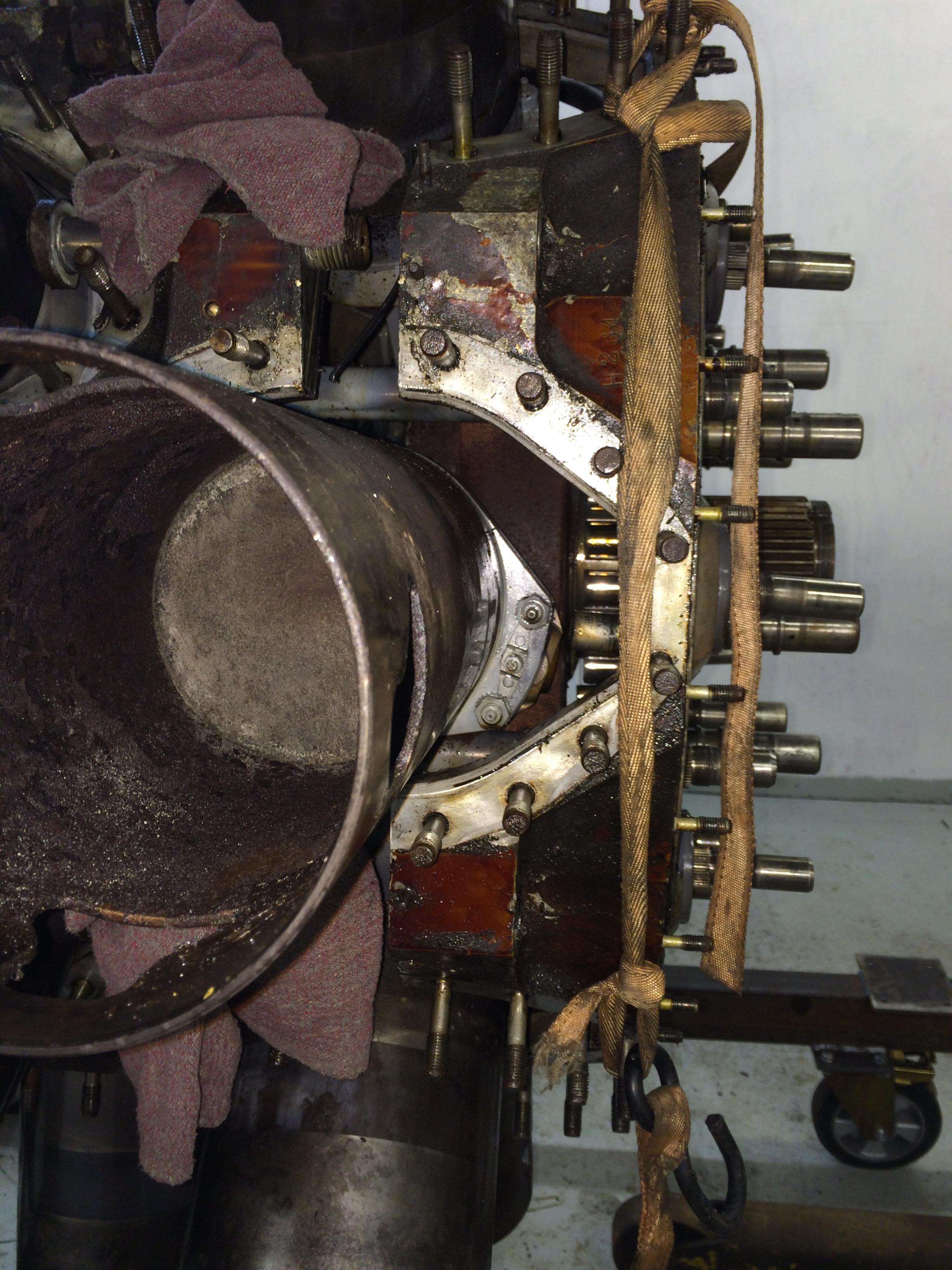
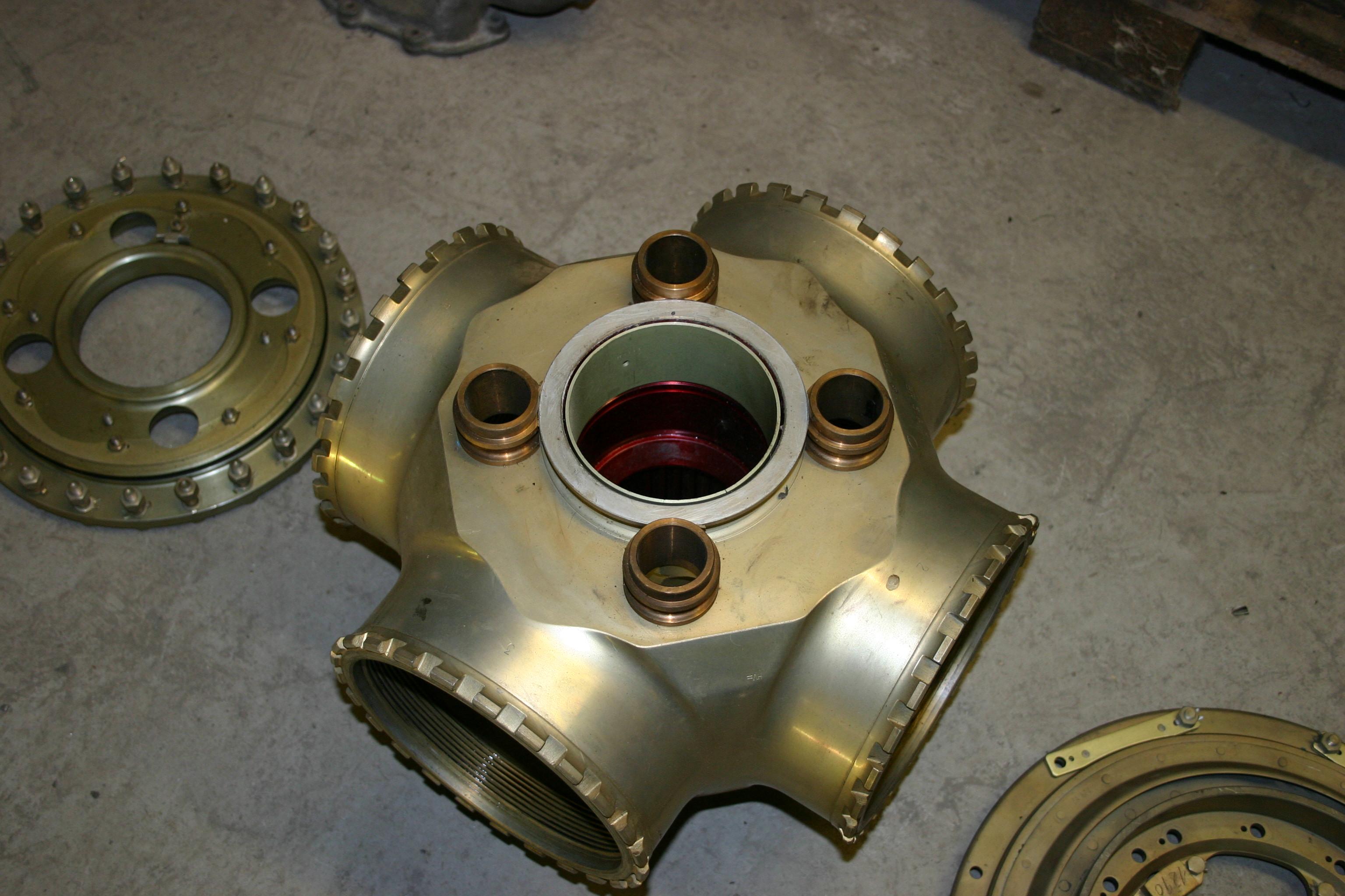
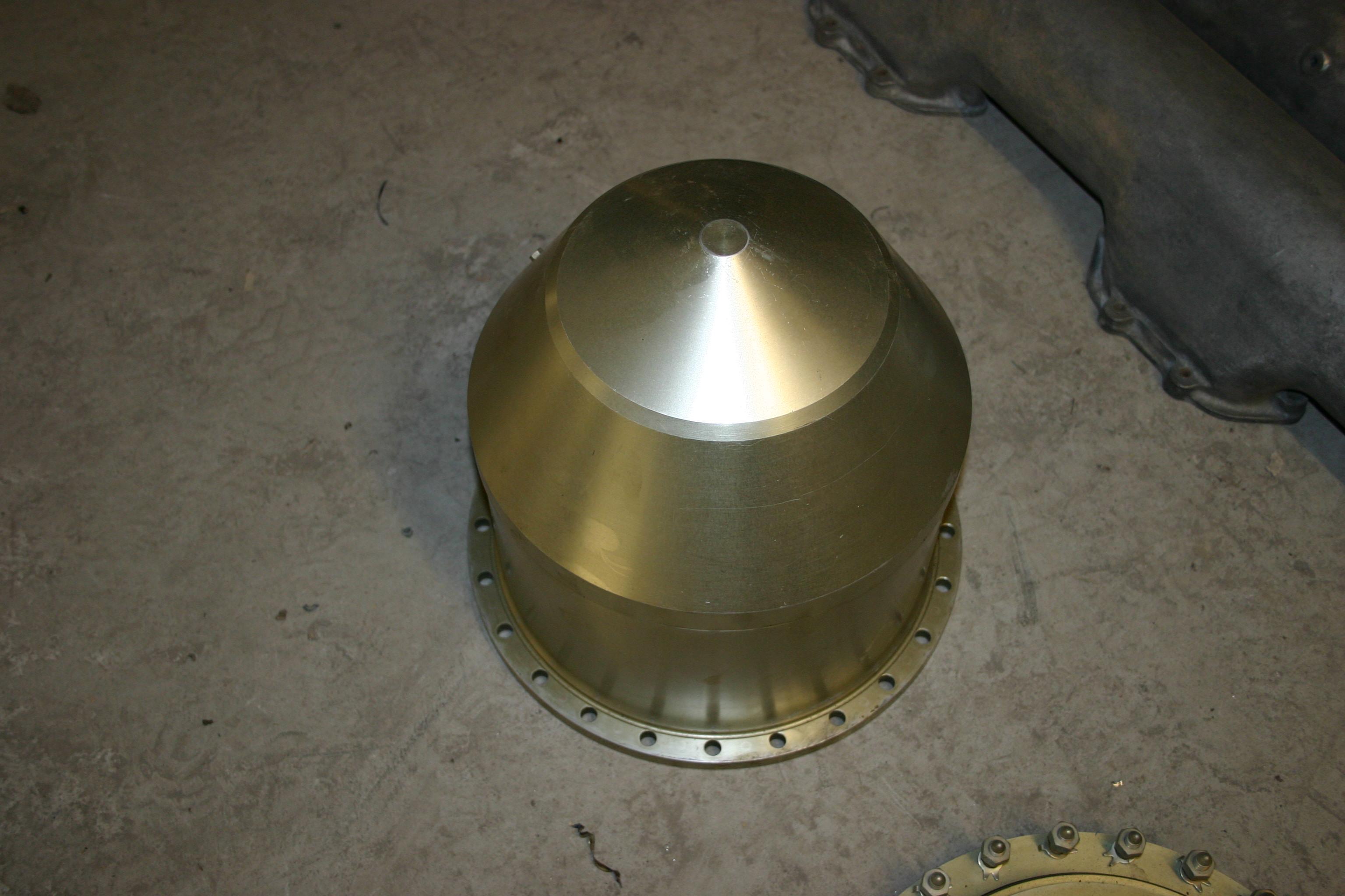
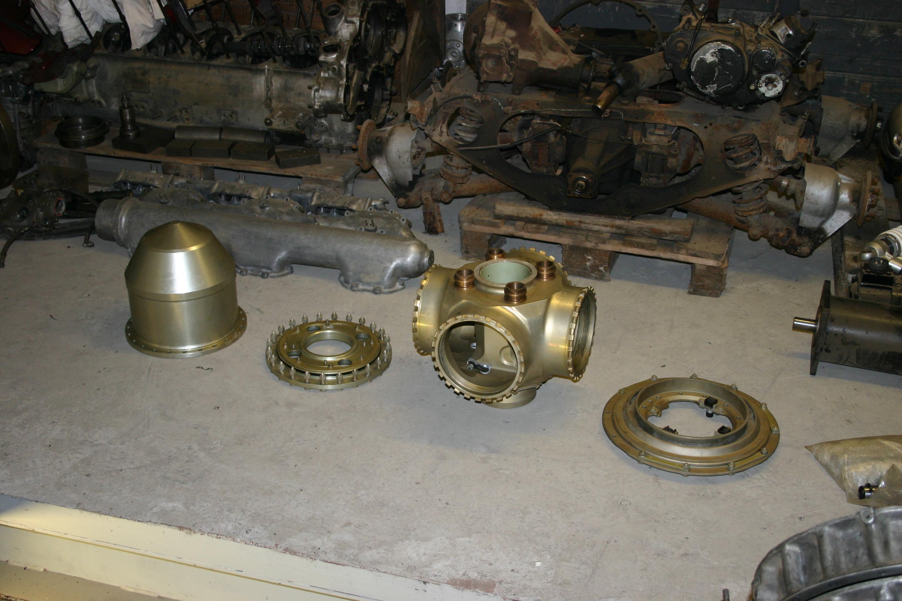
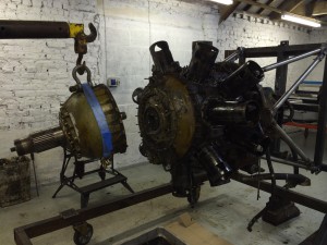
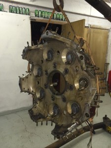
All the gears off now, next job is to remove the front section of the crank case, this will allow us to split the front section of the crankshaft.


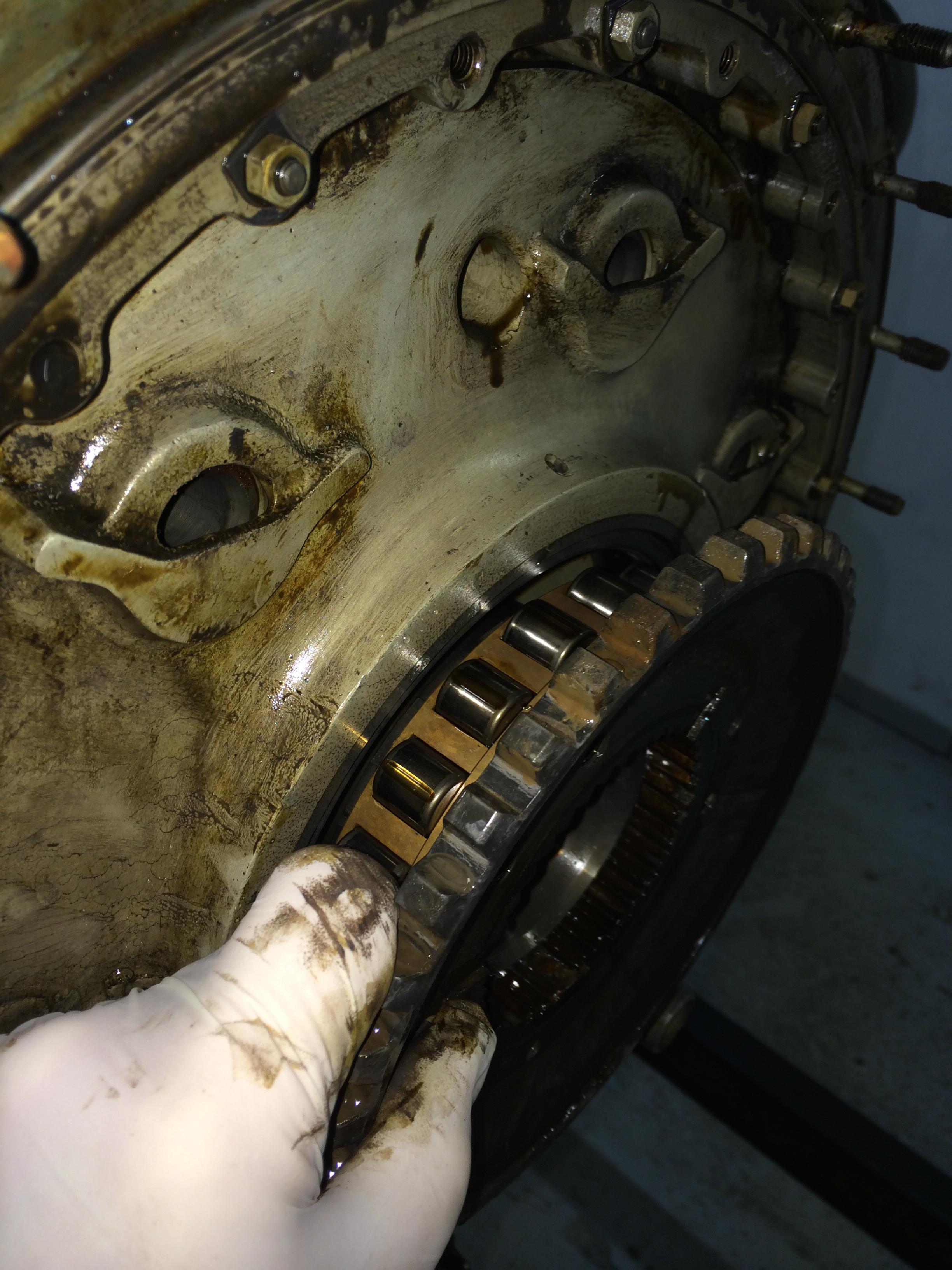
The front casing removal was quite straight forward, just get ready to catch the rollers from the front casing bearing.
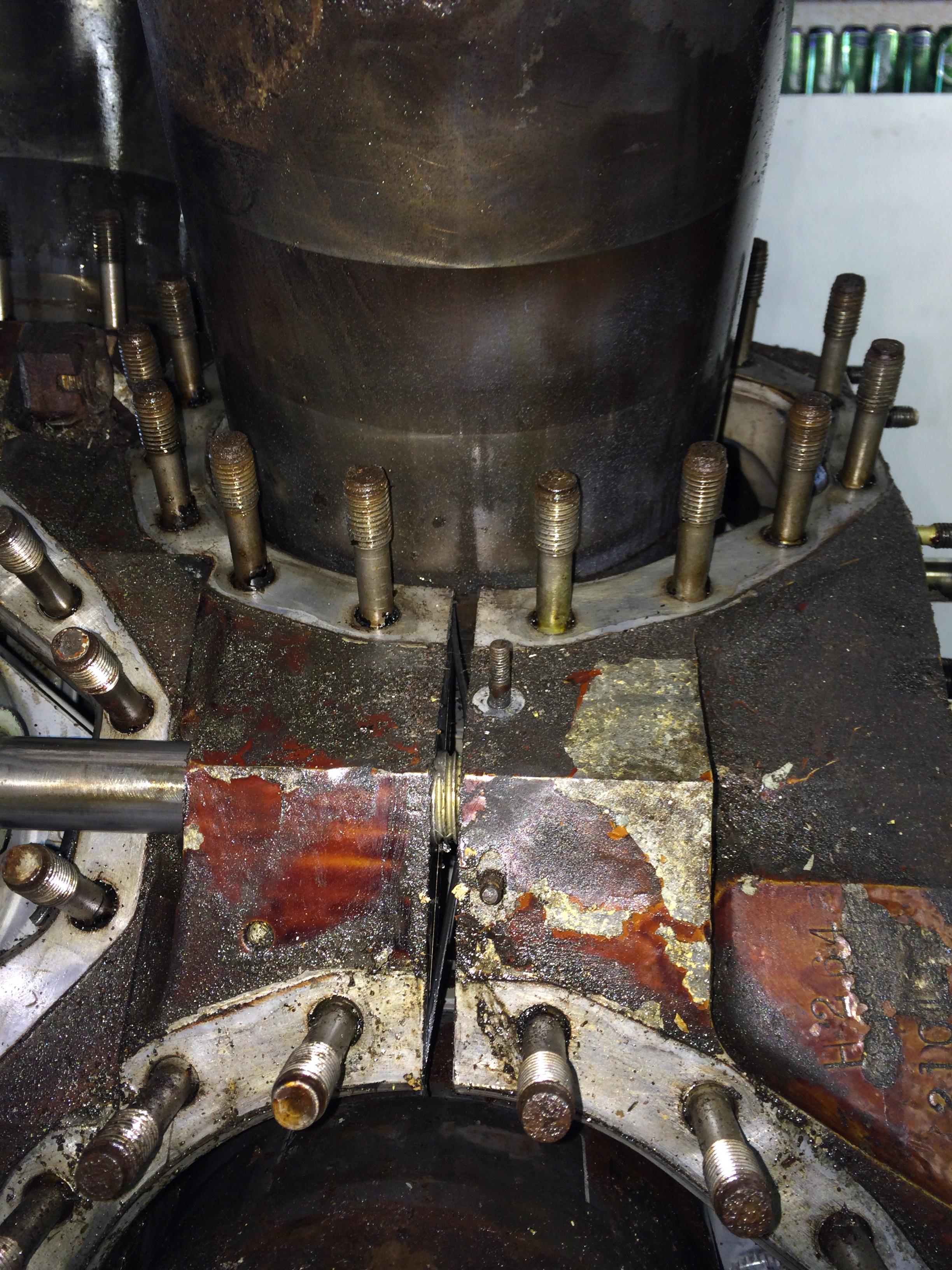
The next task is going to be a bit fiddly! we need to get the bolts out of the front part of the crank to allow us to remove the first row of con rods with the master rod, then we can remove the bottom pins from the master rod to release the rest of the cylinders.
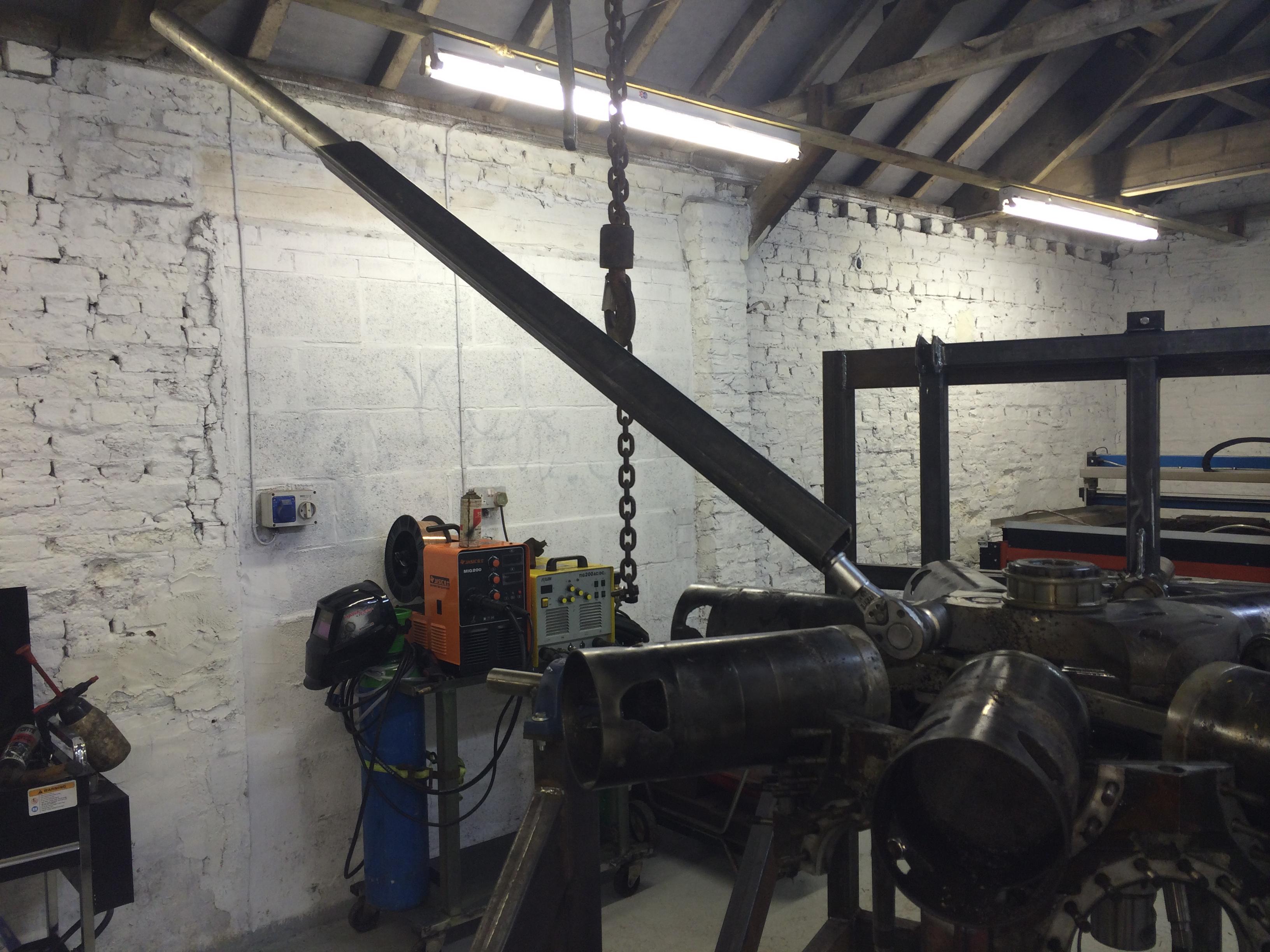
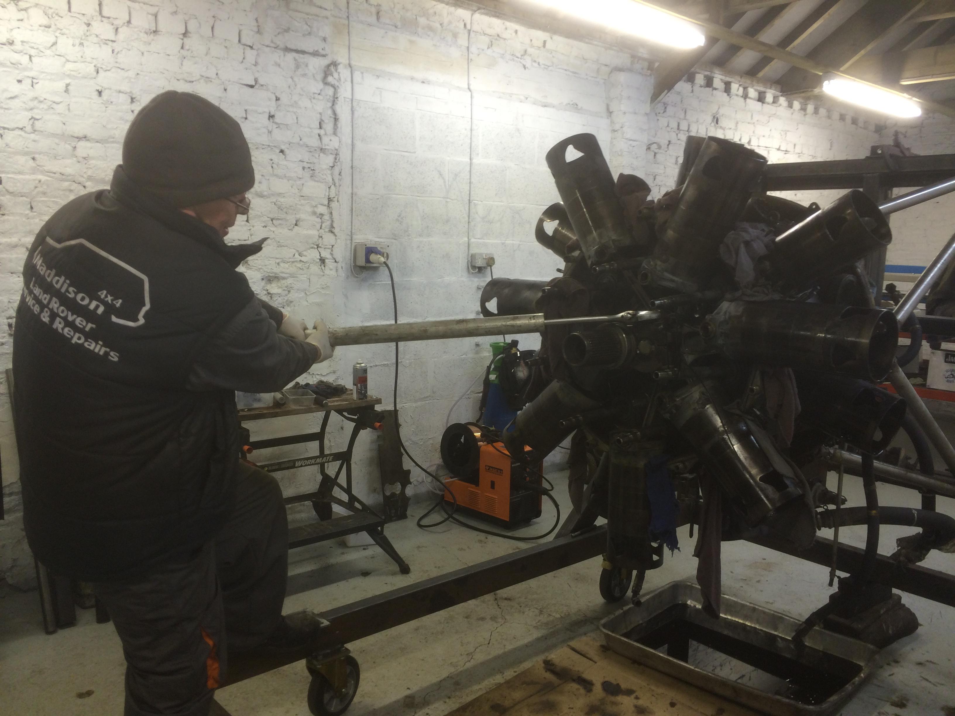
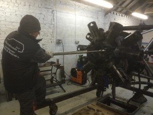
First job undo the maneton bolts, using special tool FB.168782 or in our case a 3/4″ drive ratchet and a six foot scaffolding pole! they where FT or very tight!
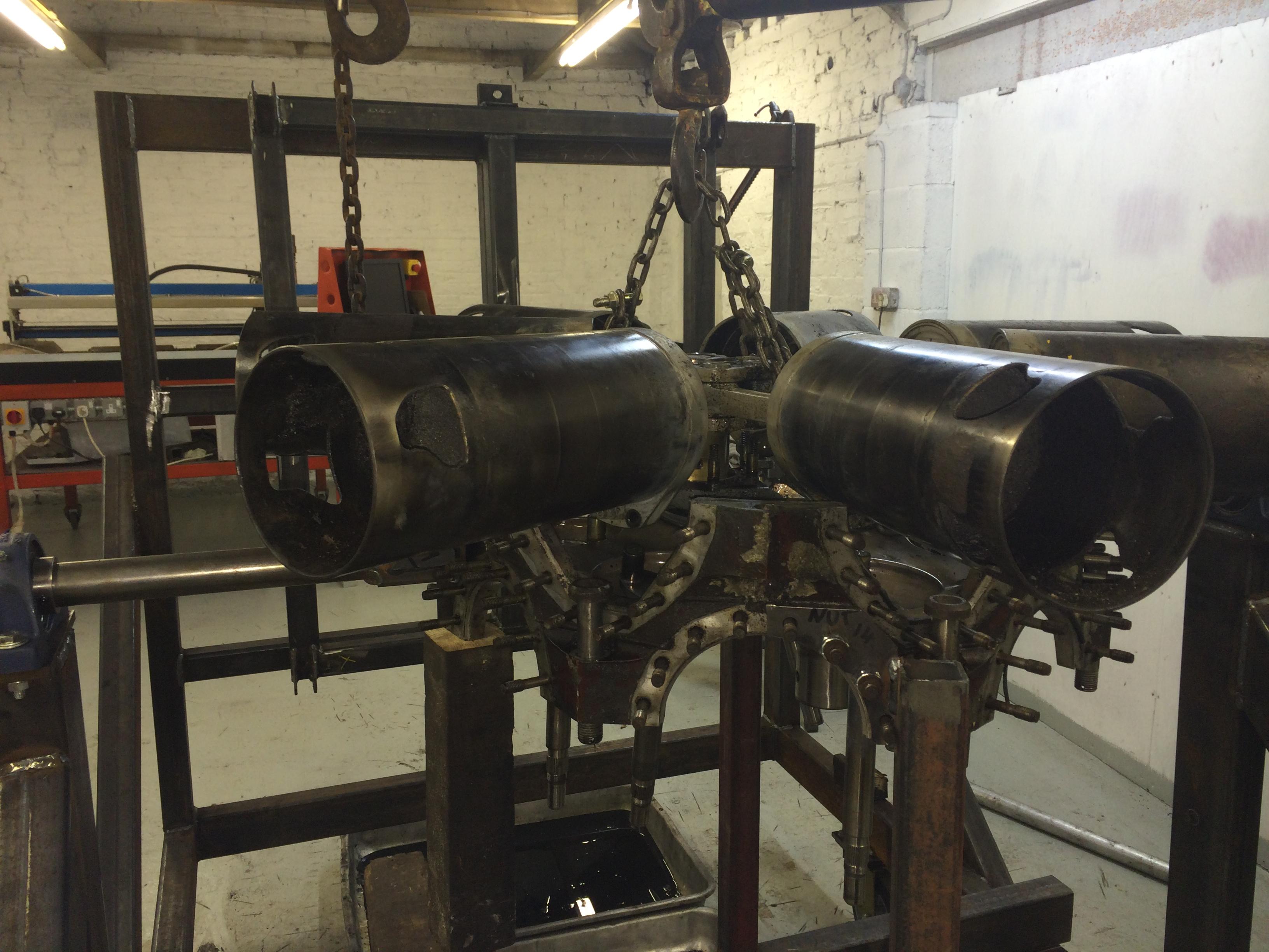
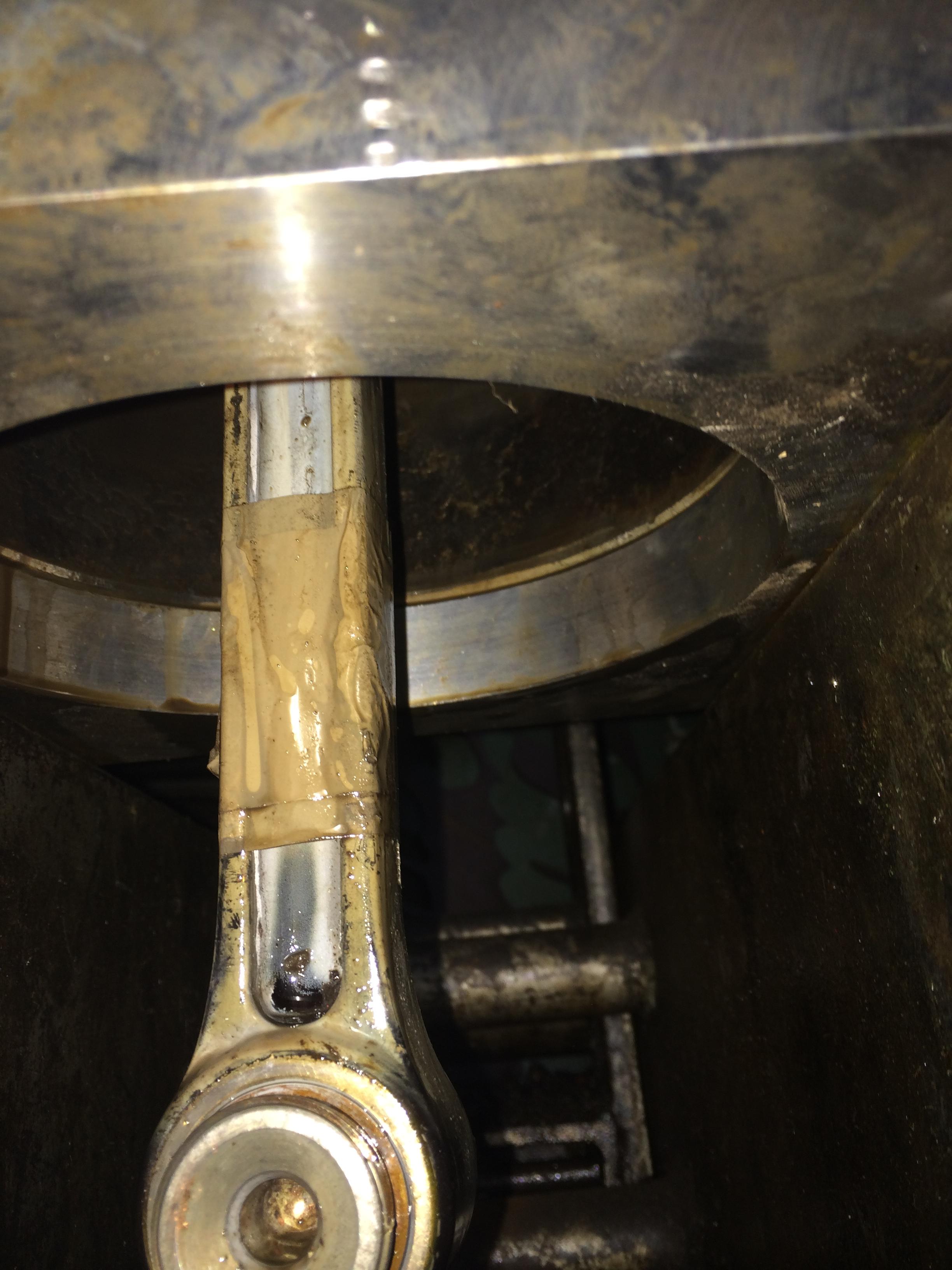
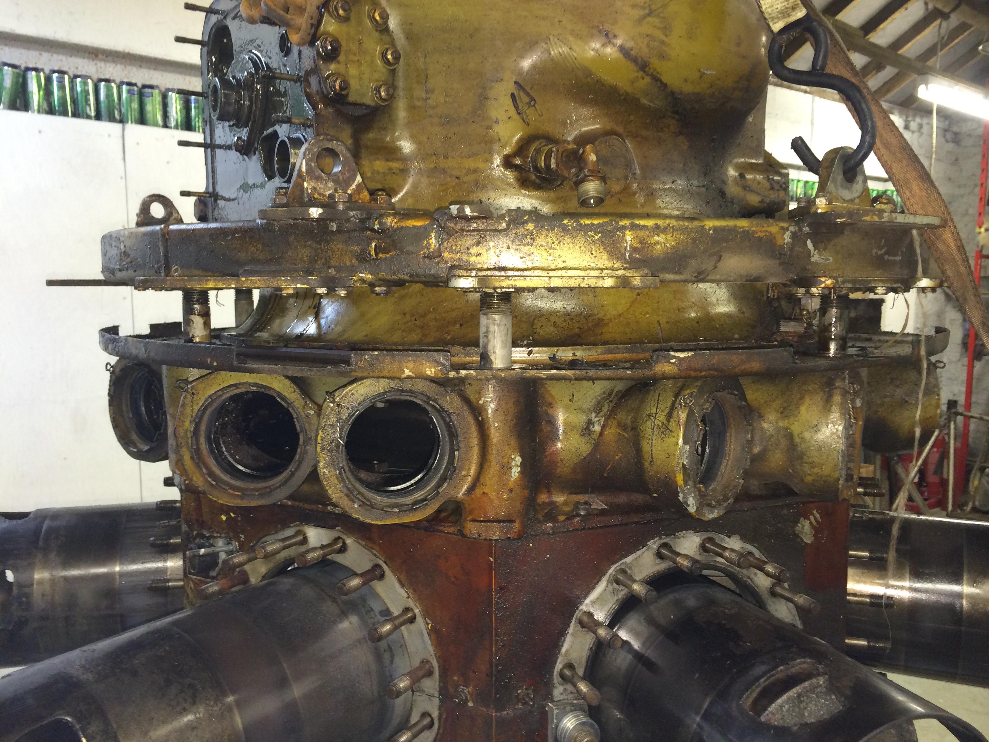
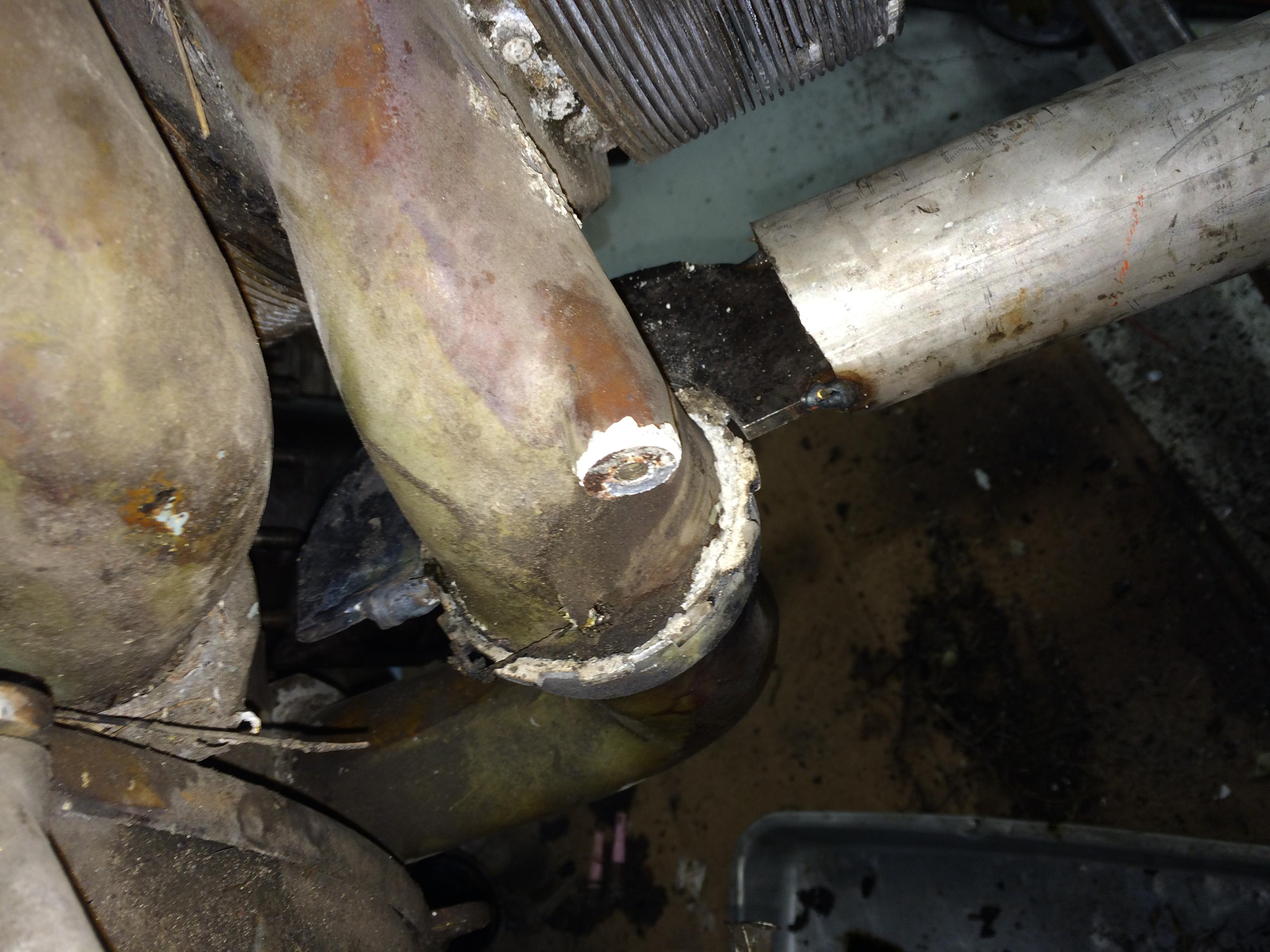
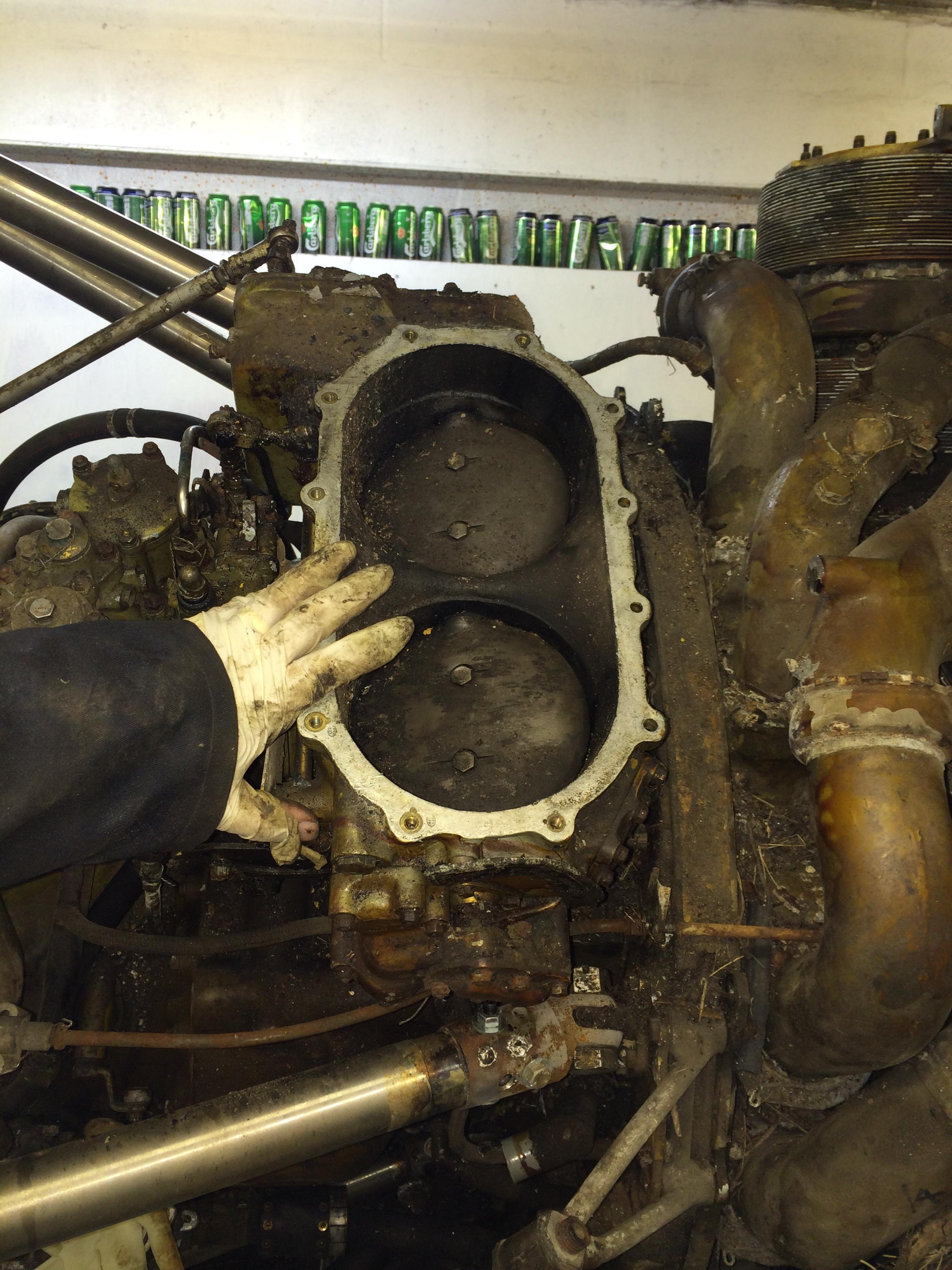
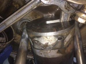
The rear bolt of the front maneton came straight out, the problem with the front bolt was that it fouled No.6 sleeve. First we undid all of the sleeve ball joints, which gave us about 10′ of rotation of the engine, this was still not quite enough for us to get the front bolt out.
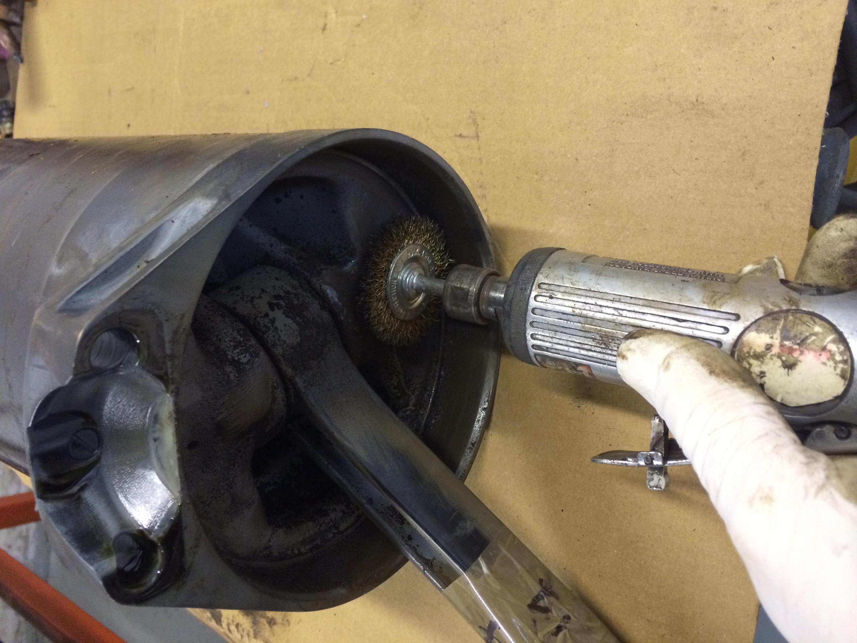
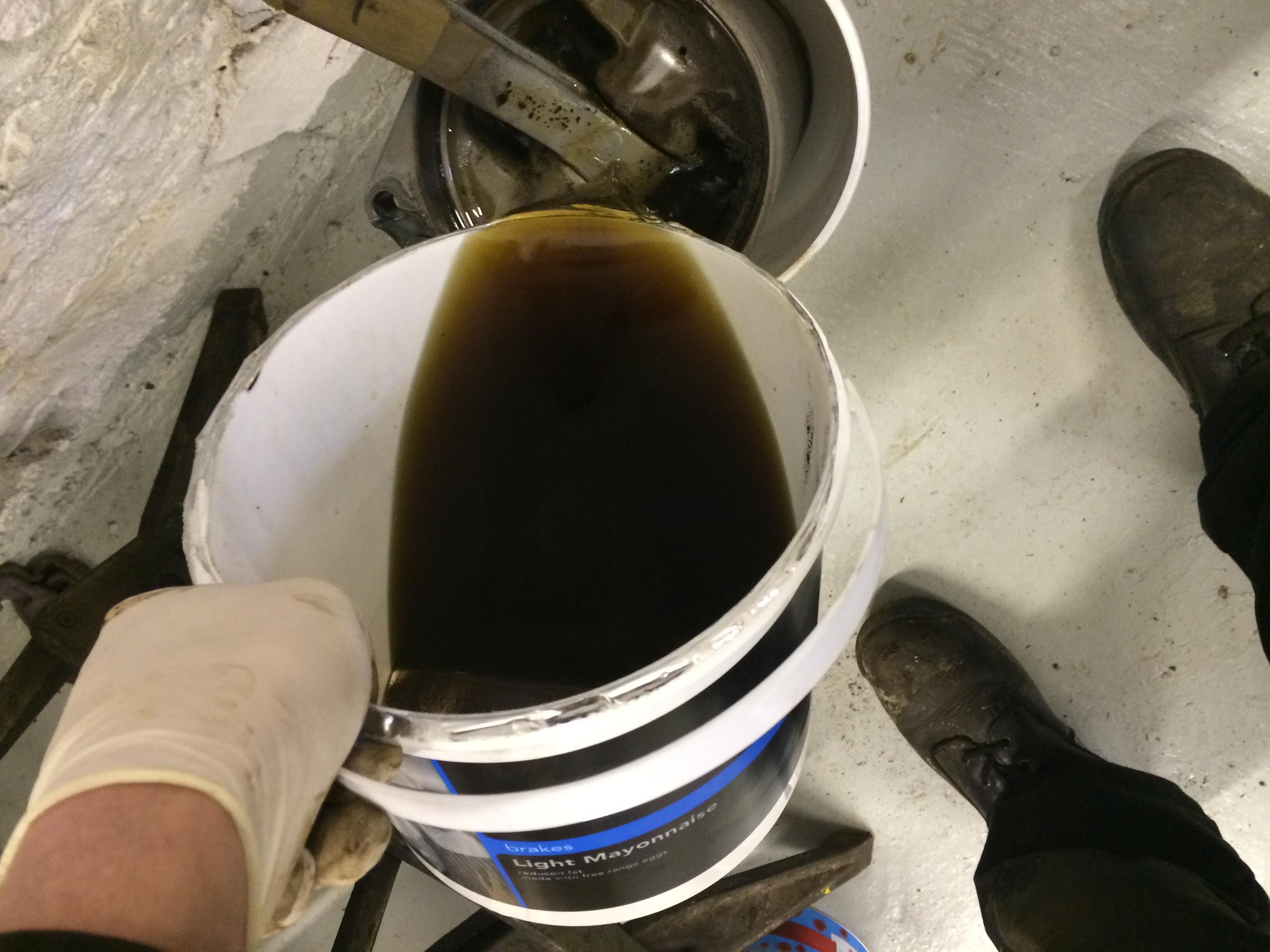
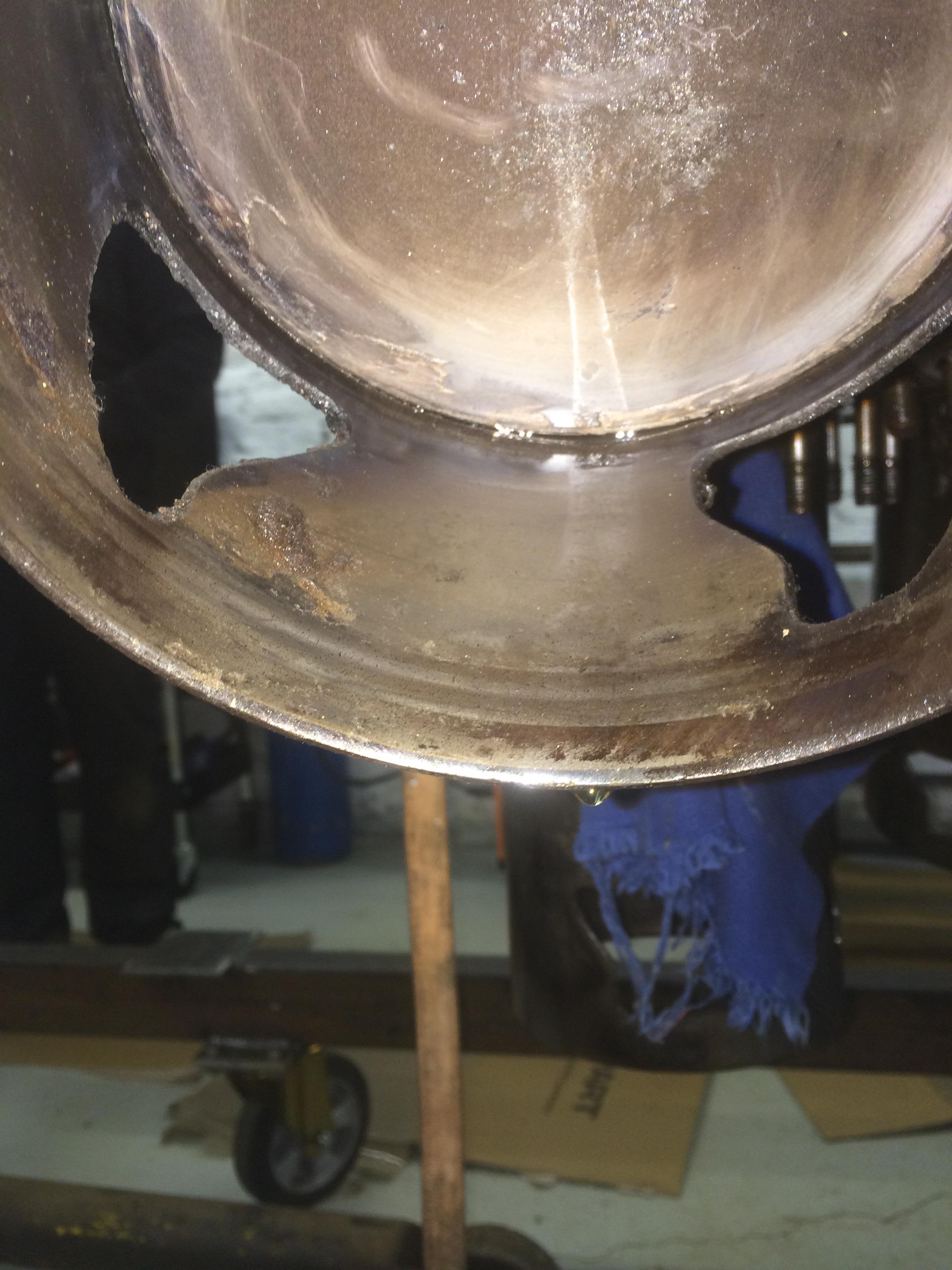
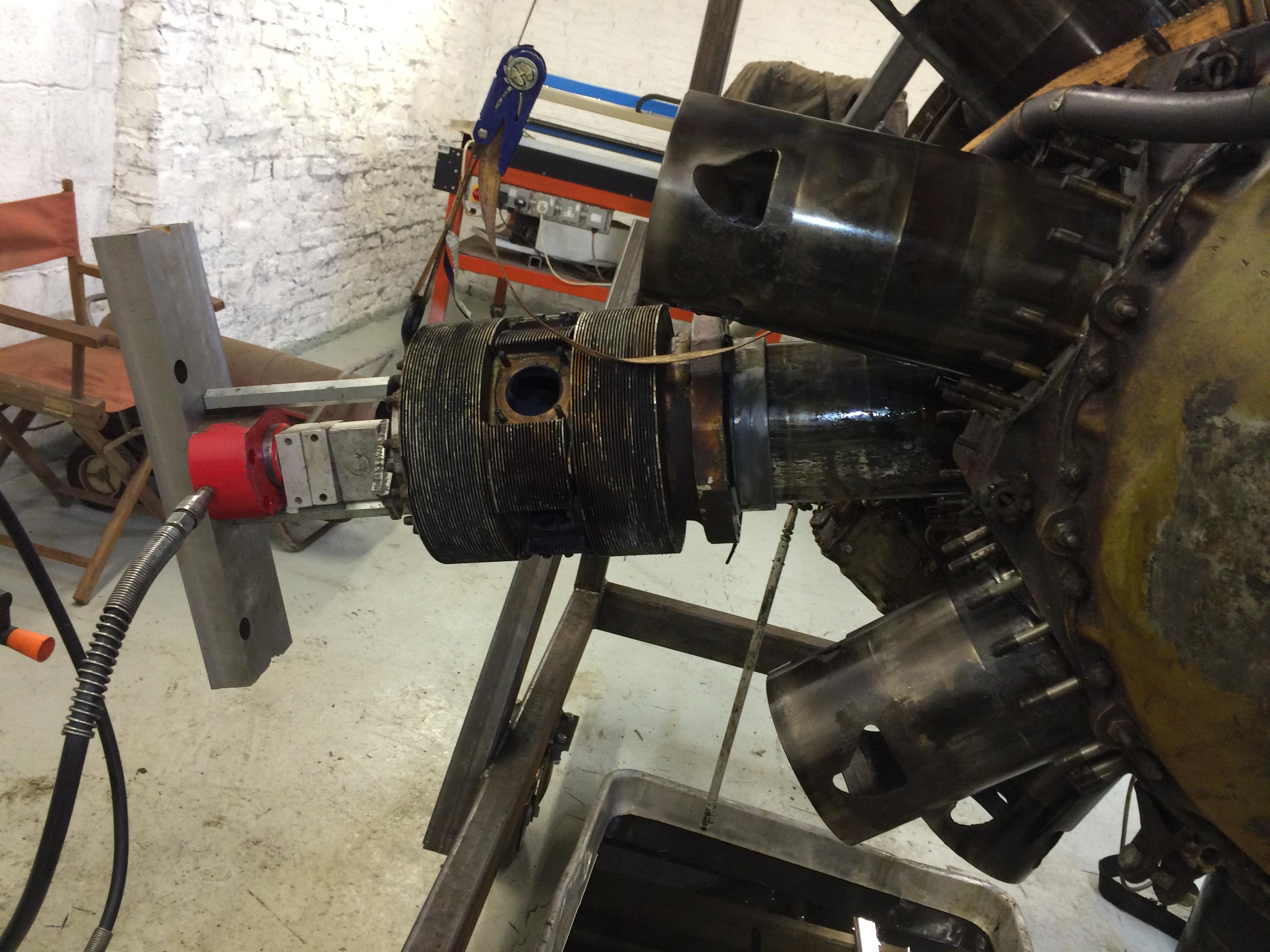
So we had move No.6 sleeve down a bit to give us clearance. We mixed up our special brew of Forte Diesel Injector cleaner and Variable Vane Turbo Cleaner 50/50 mix and flooded the back of No.6 piston.
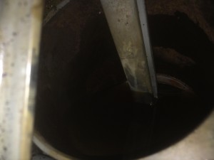
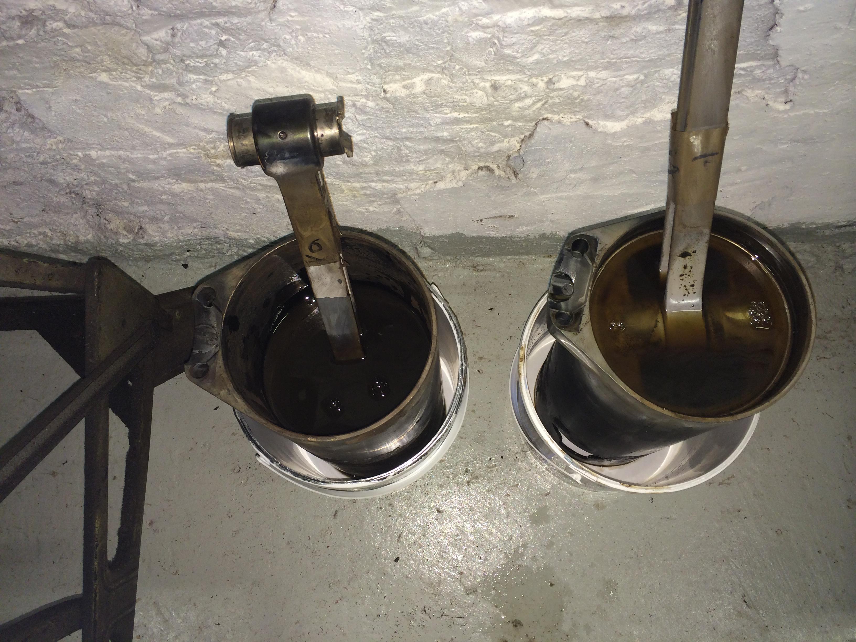
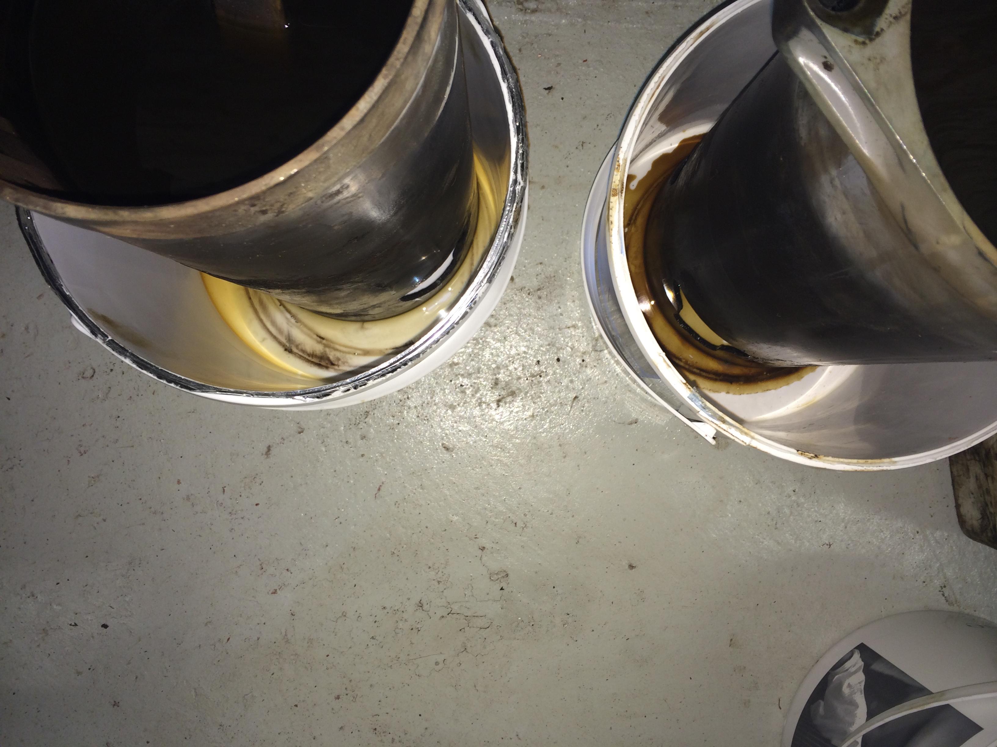
After a twelve hour soak, the special brew had worked its way through and was dripping out of the sleeve.

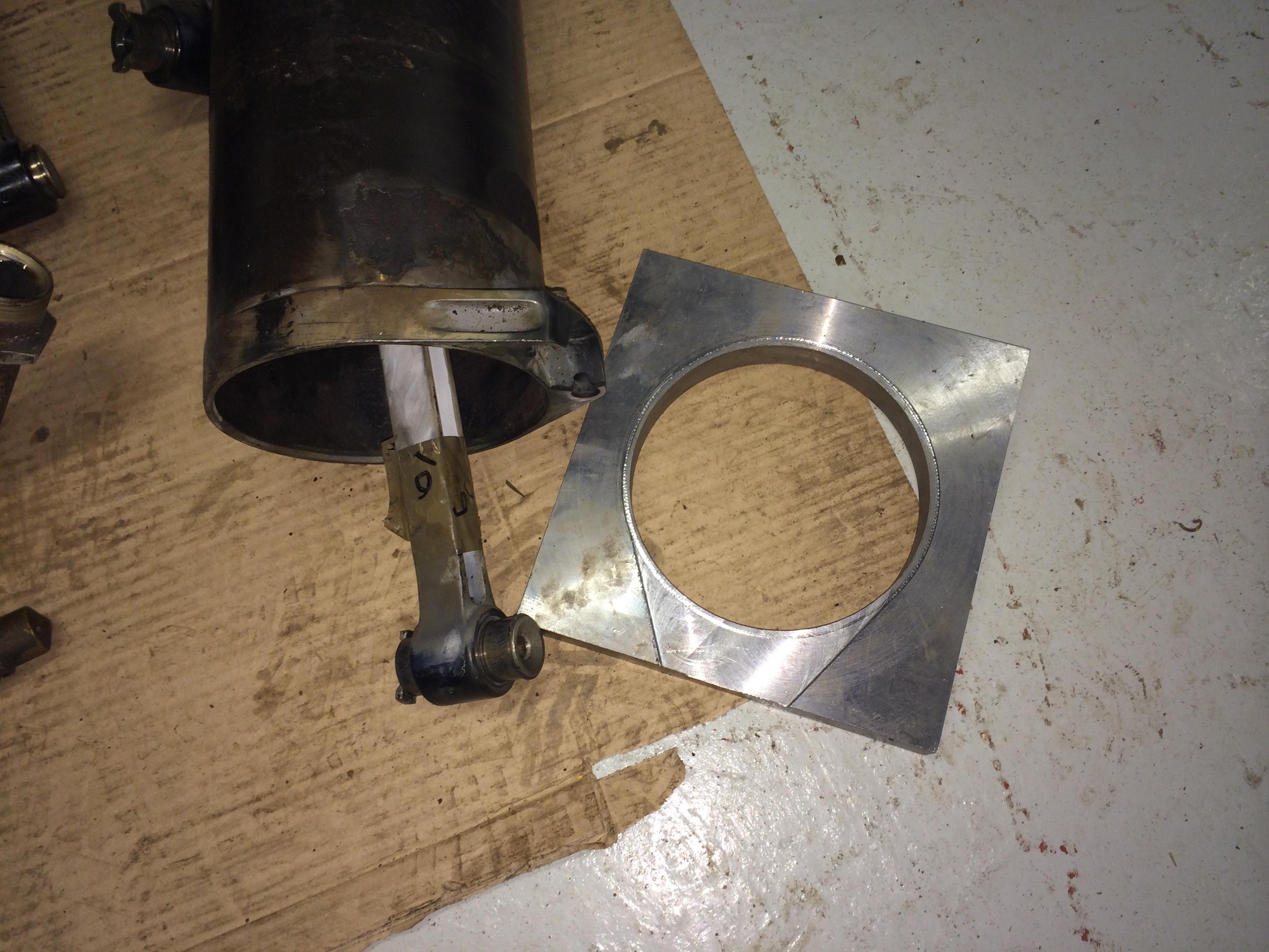
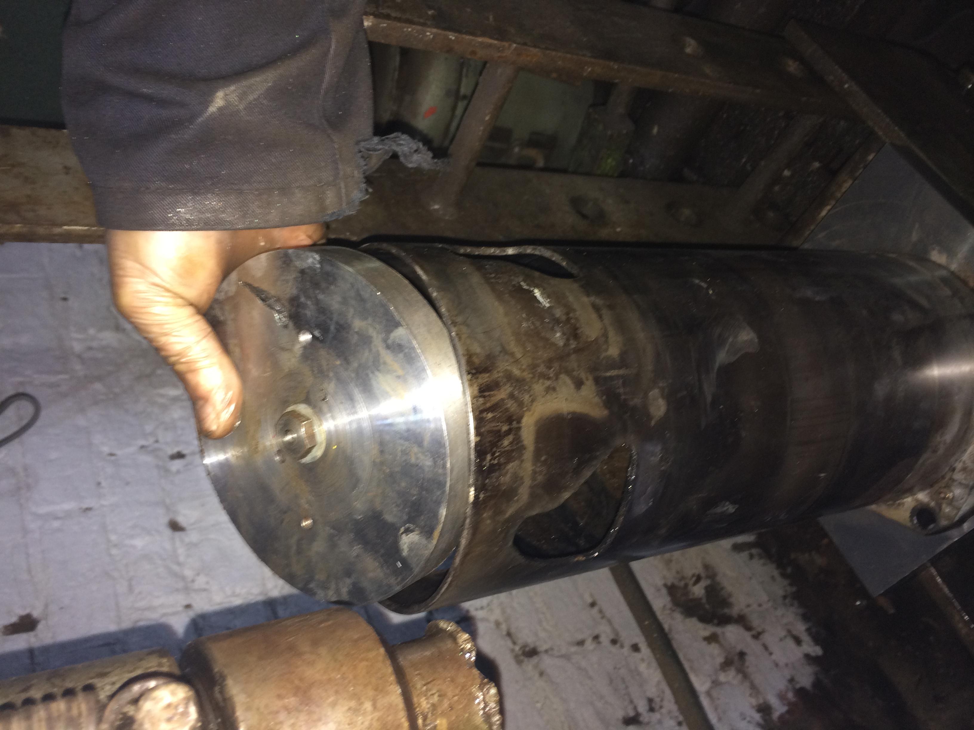
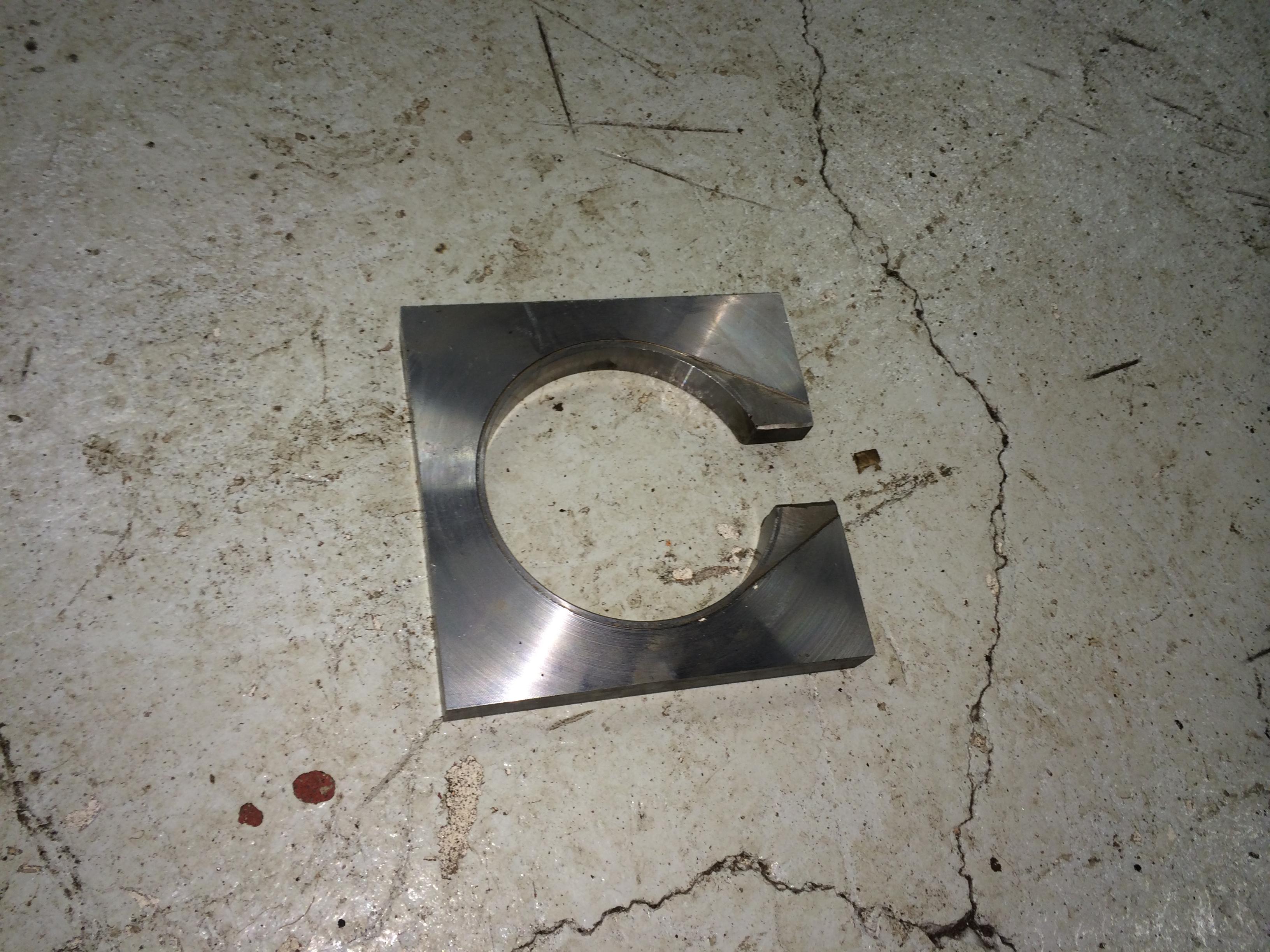
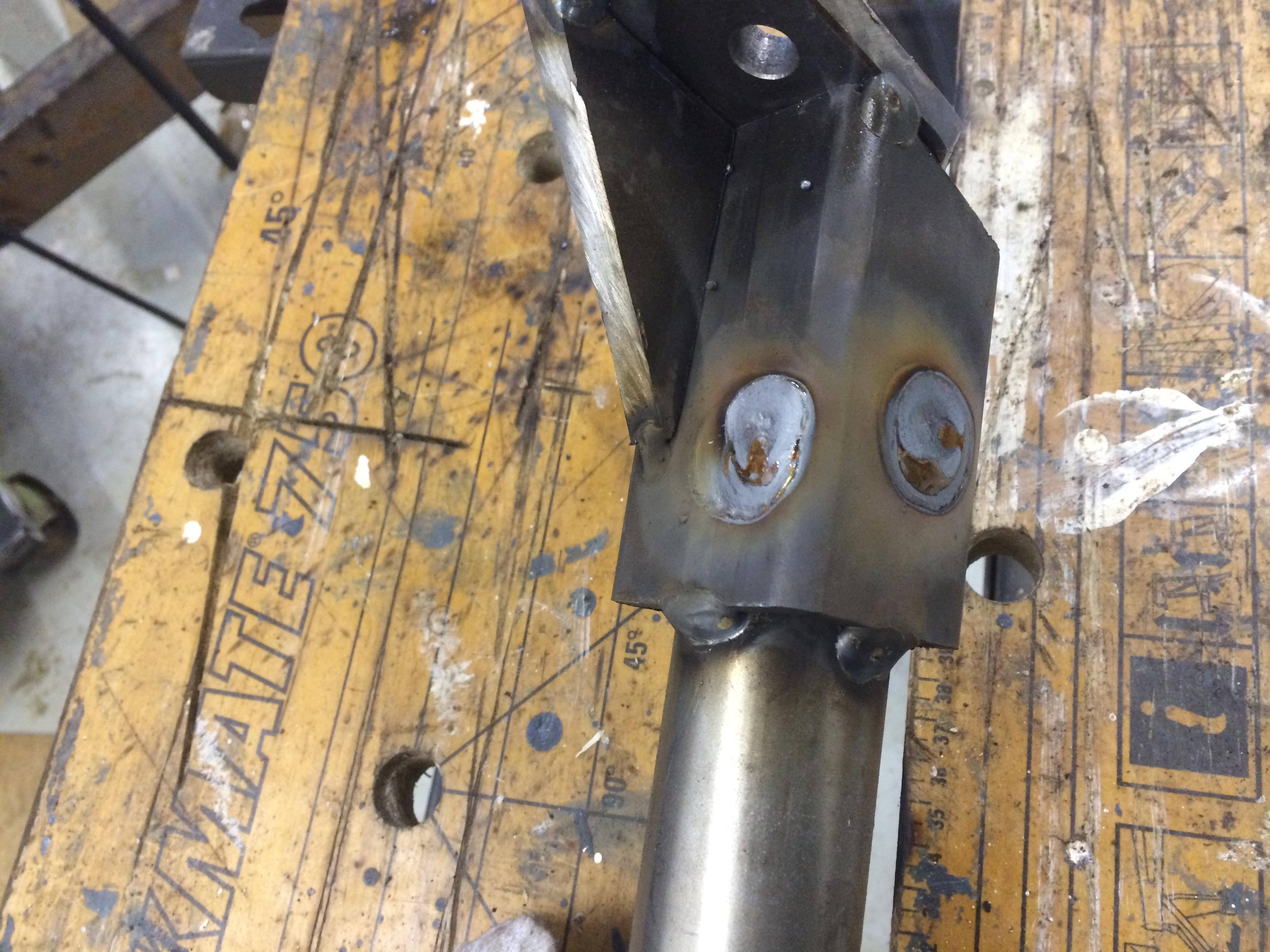
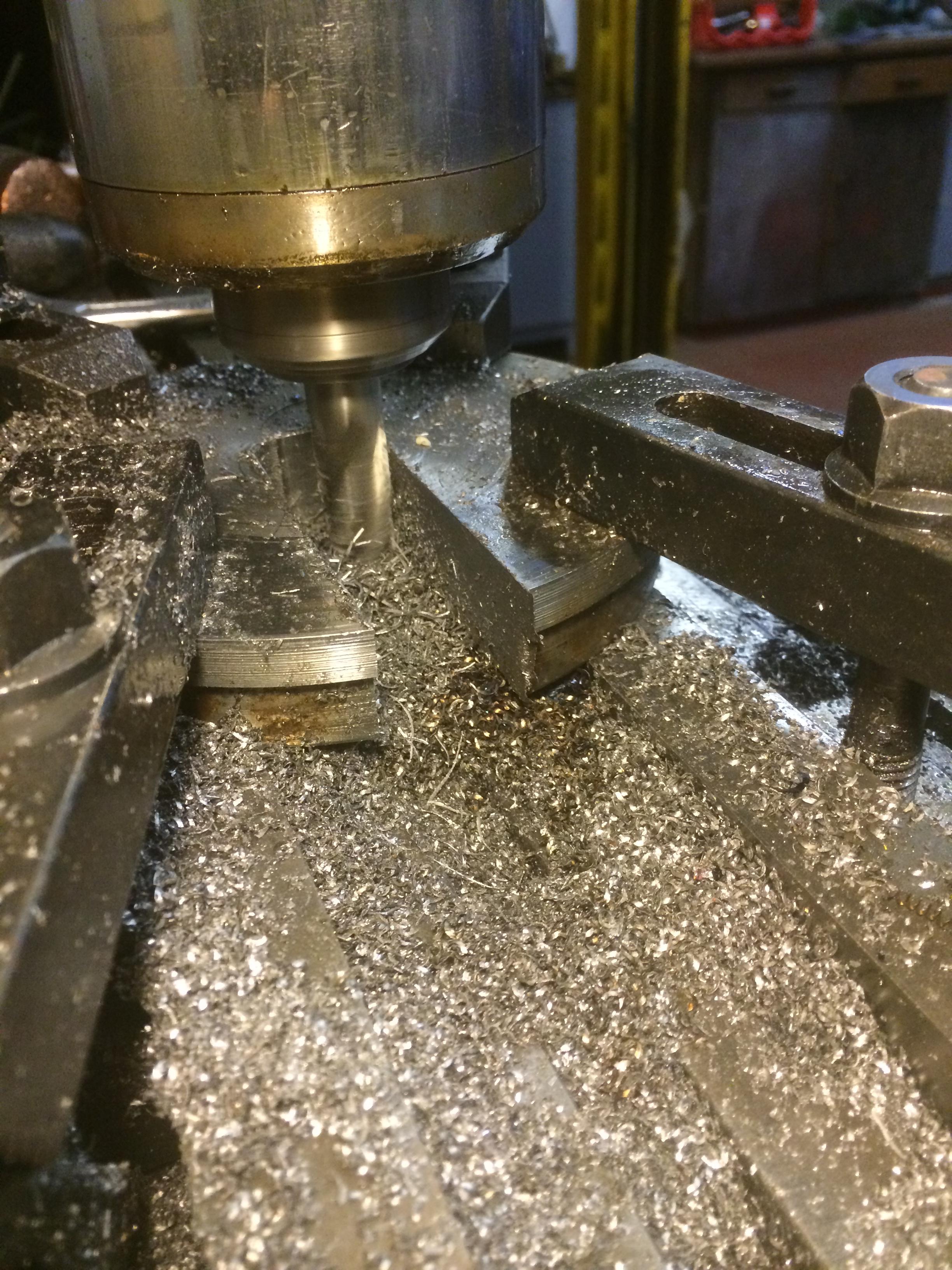
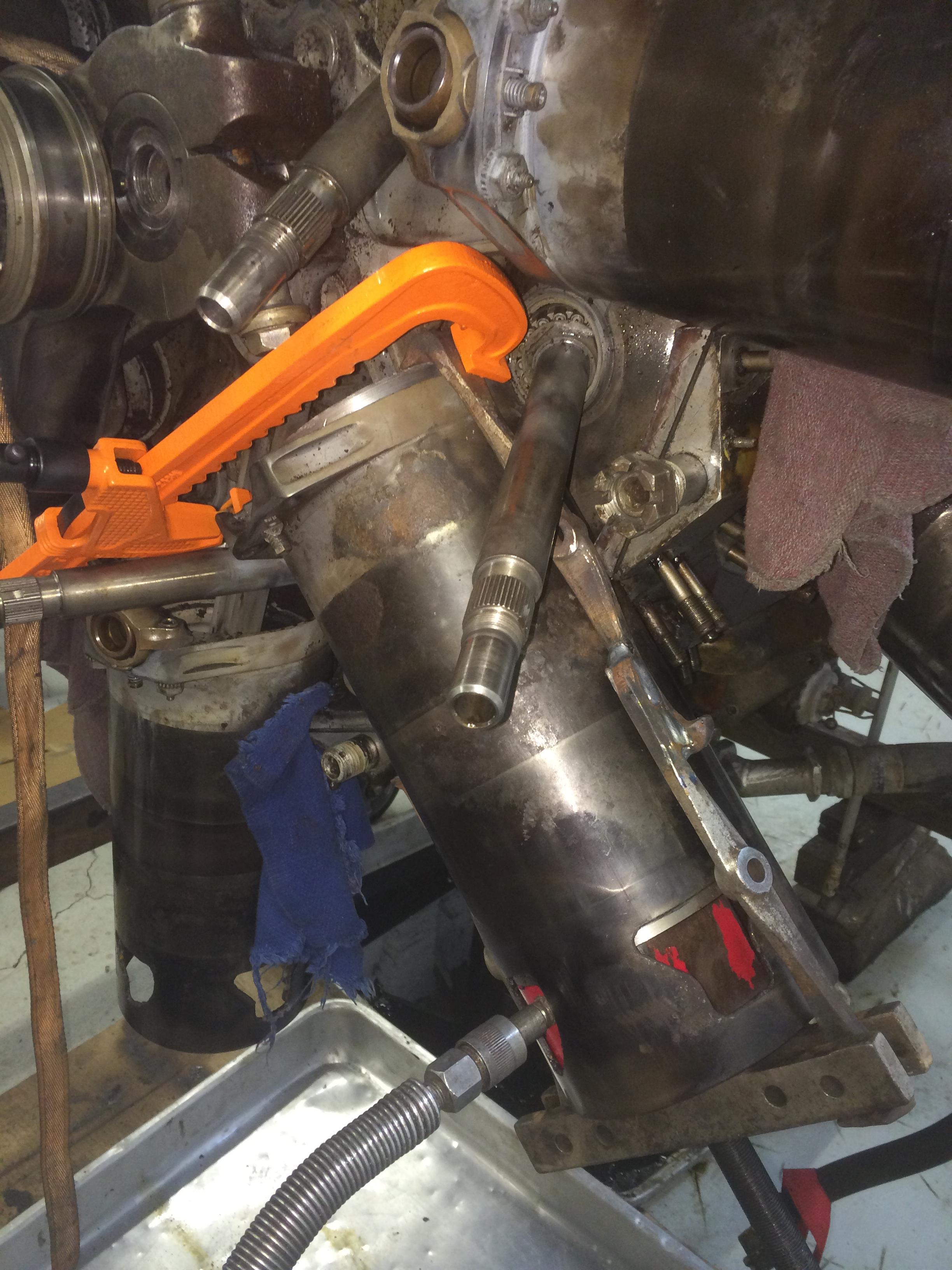
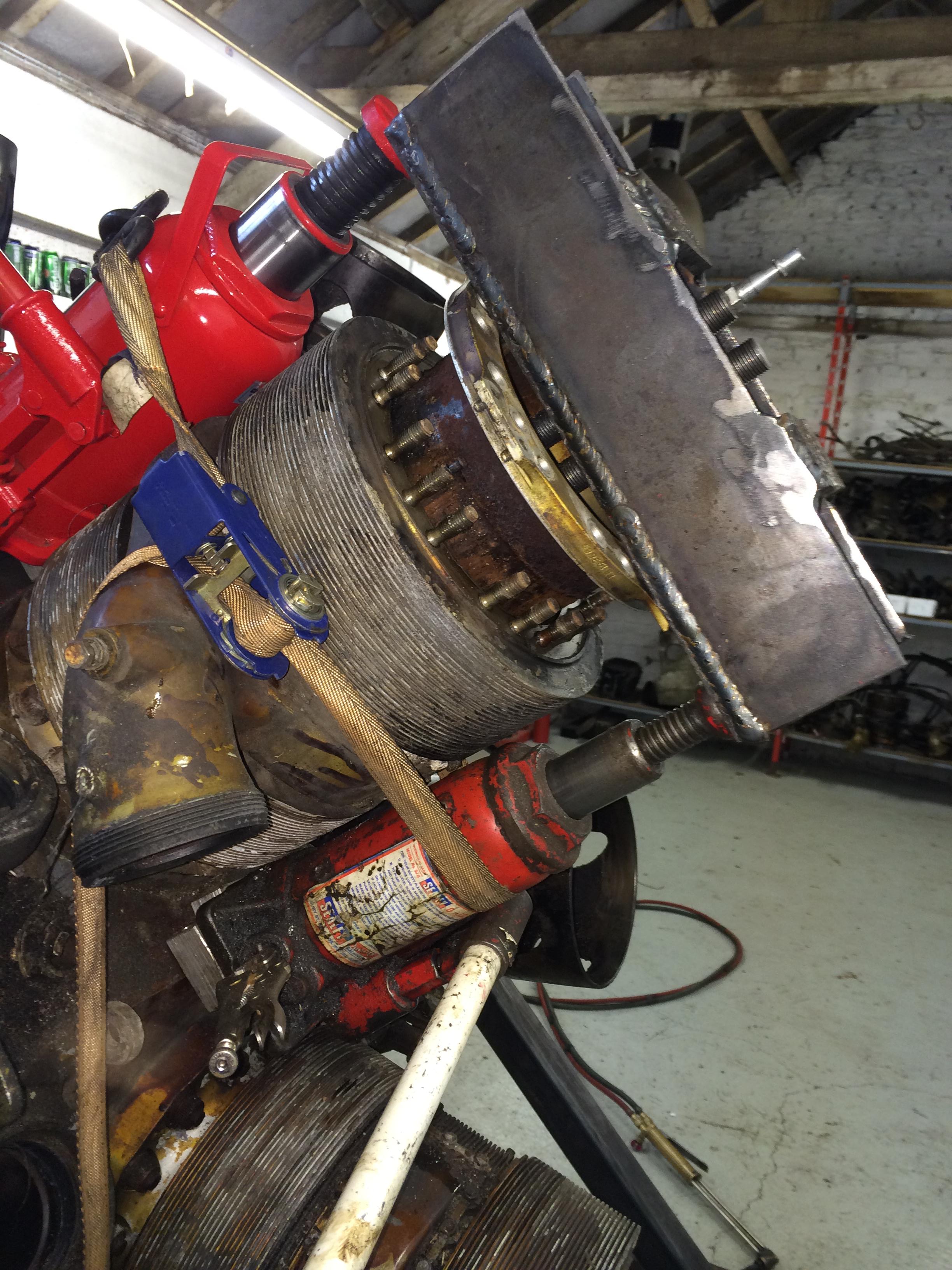
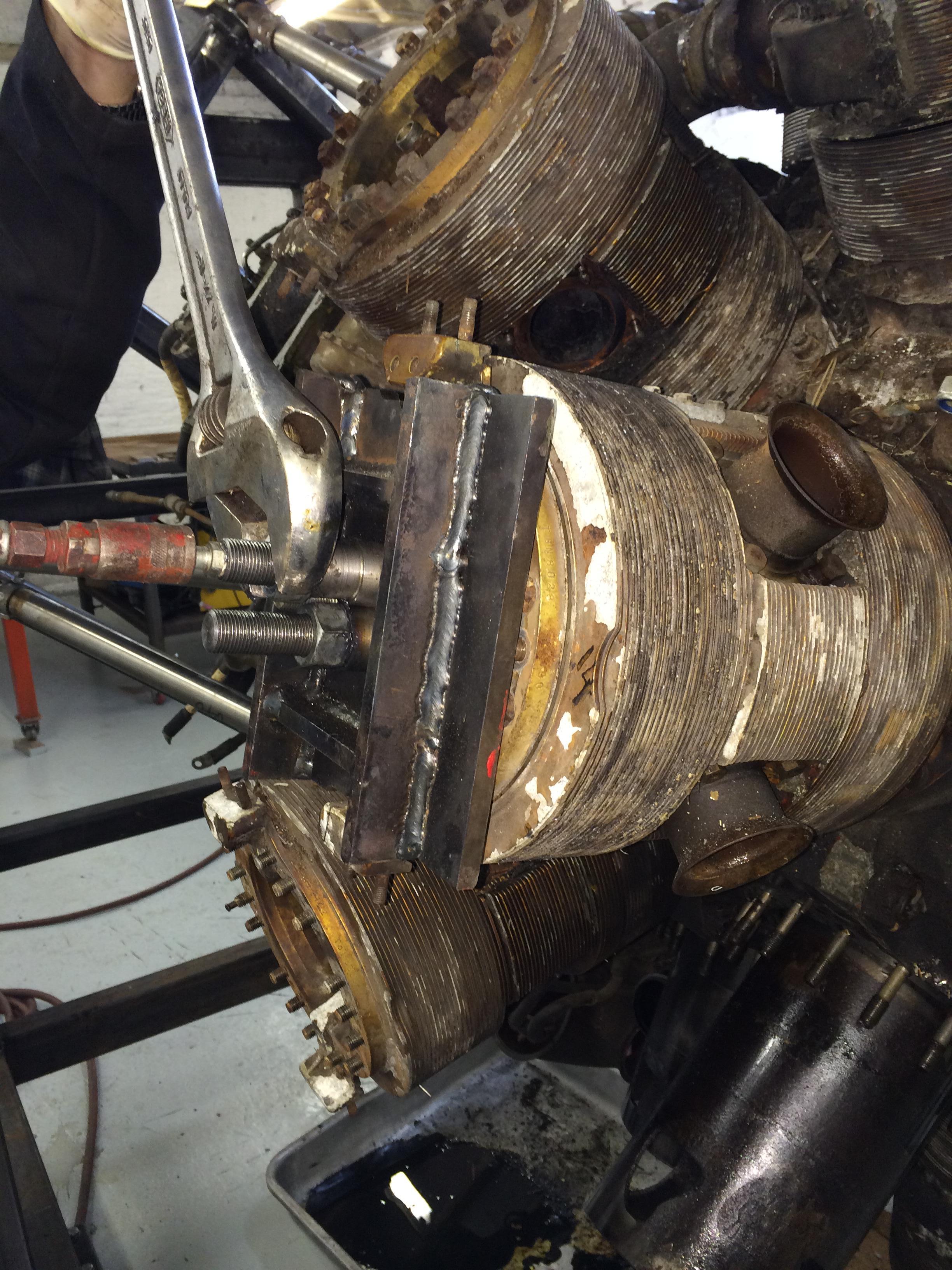
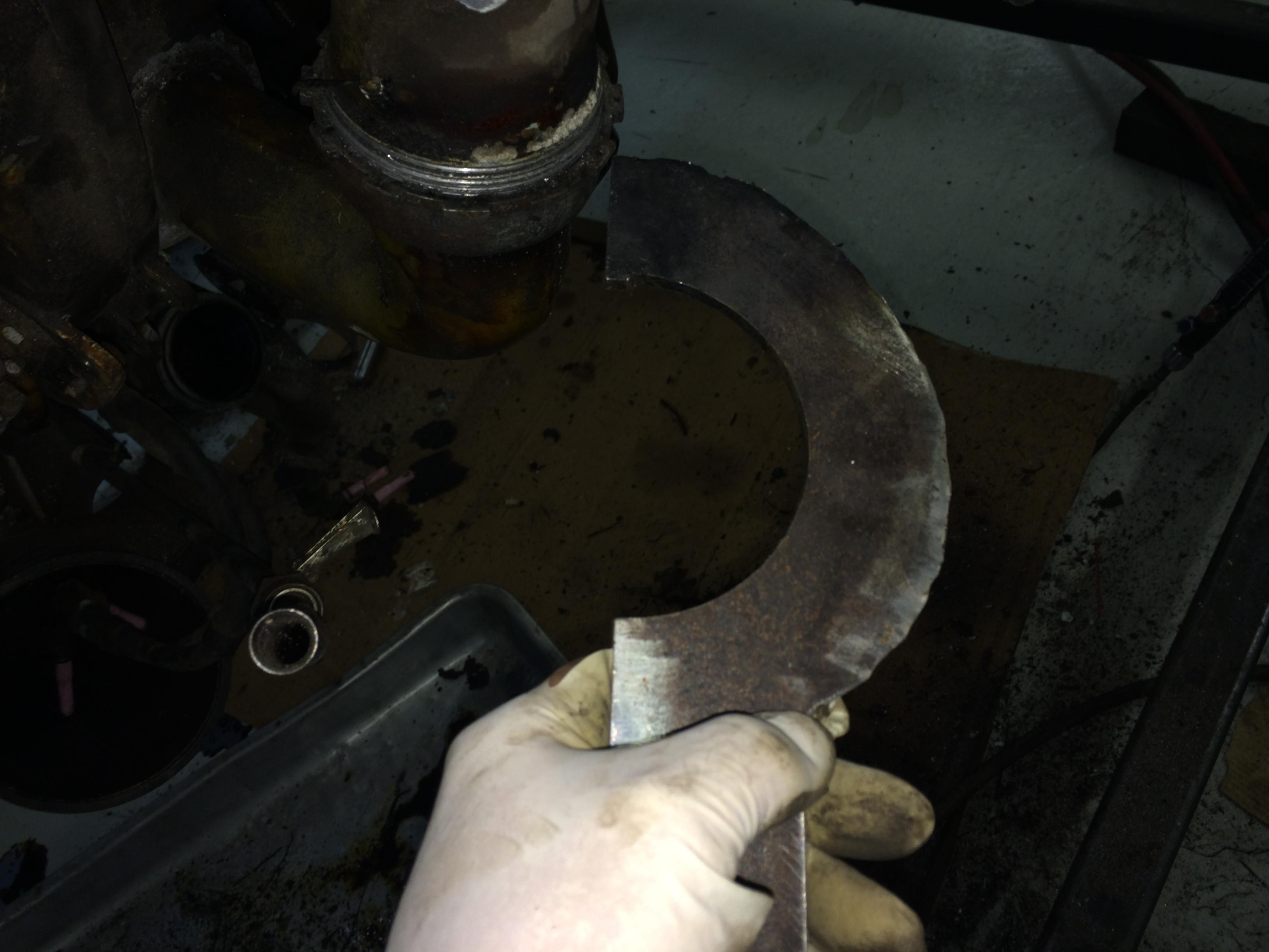
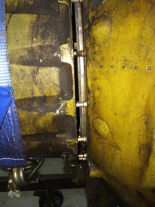
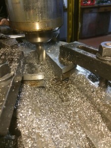
Next we had to make up a puller to move the sleeve, we altered one of the cylinder removal tools by milling a slot in it to allow us to fit it at the base of the sleeve around the con rod.
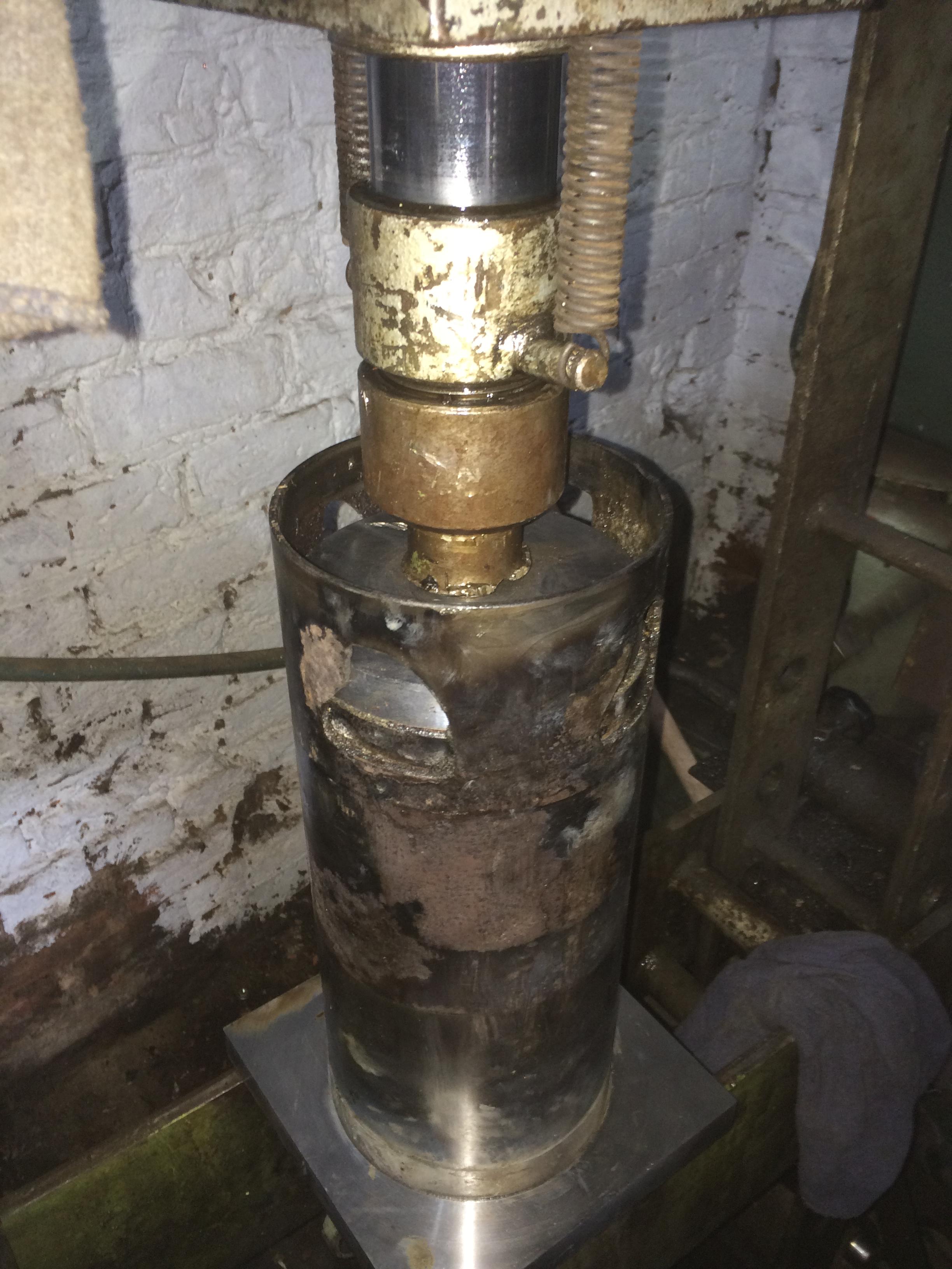
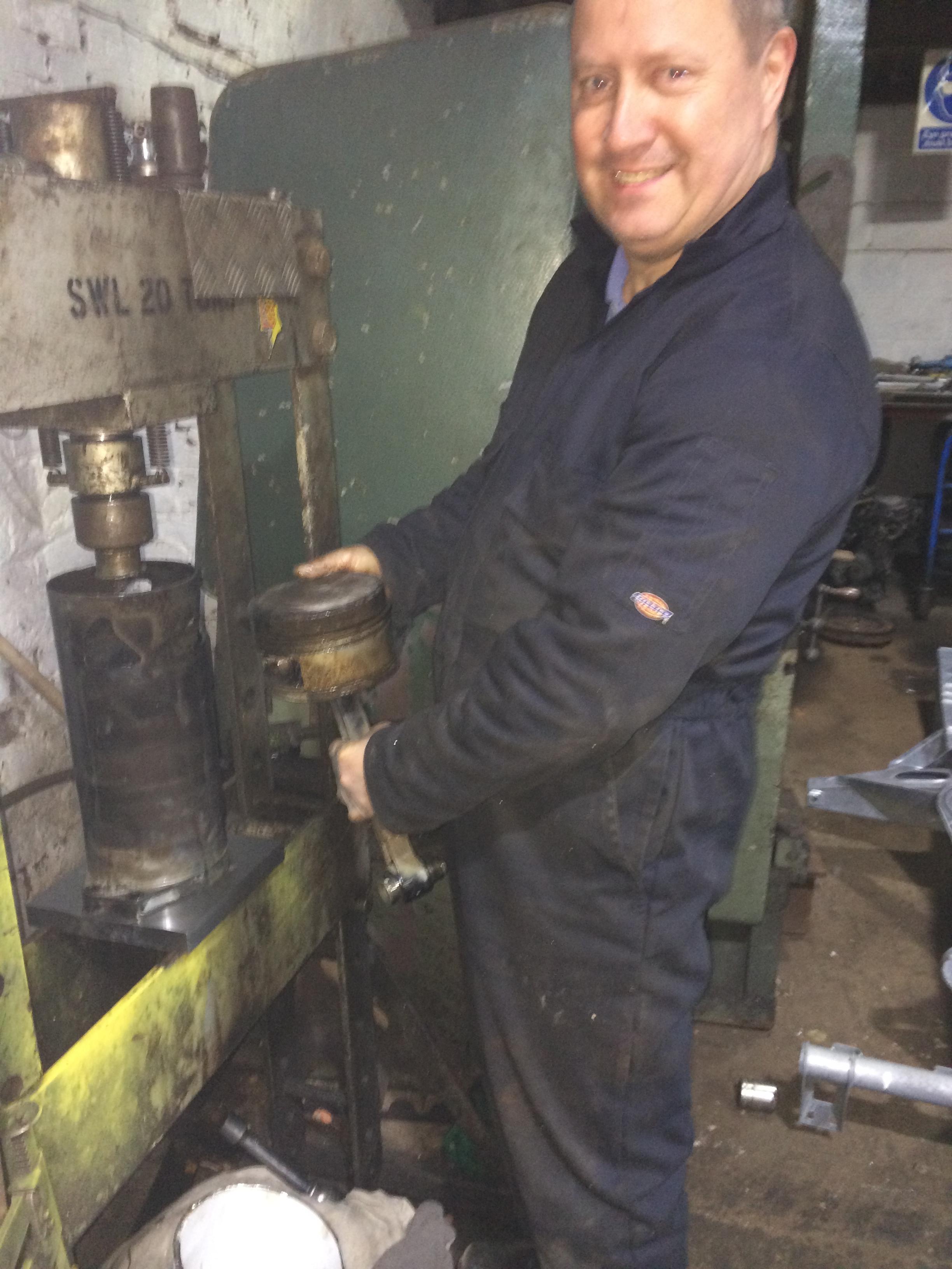
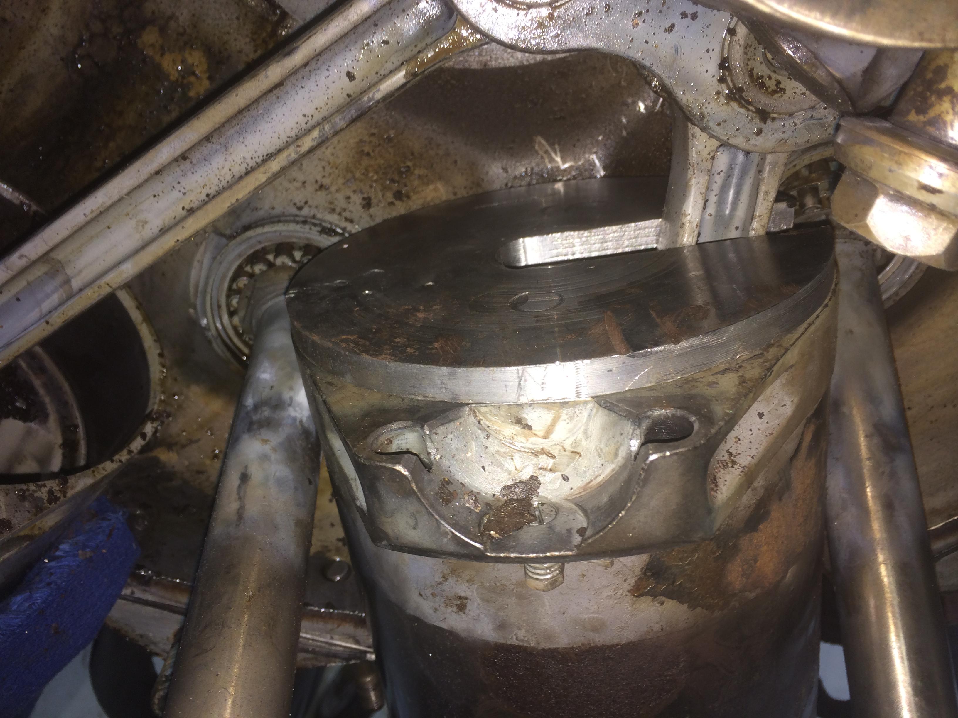
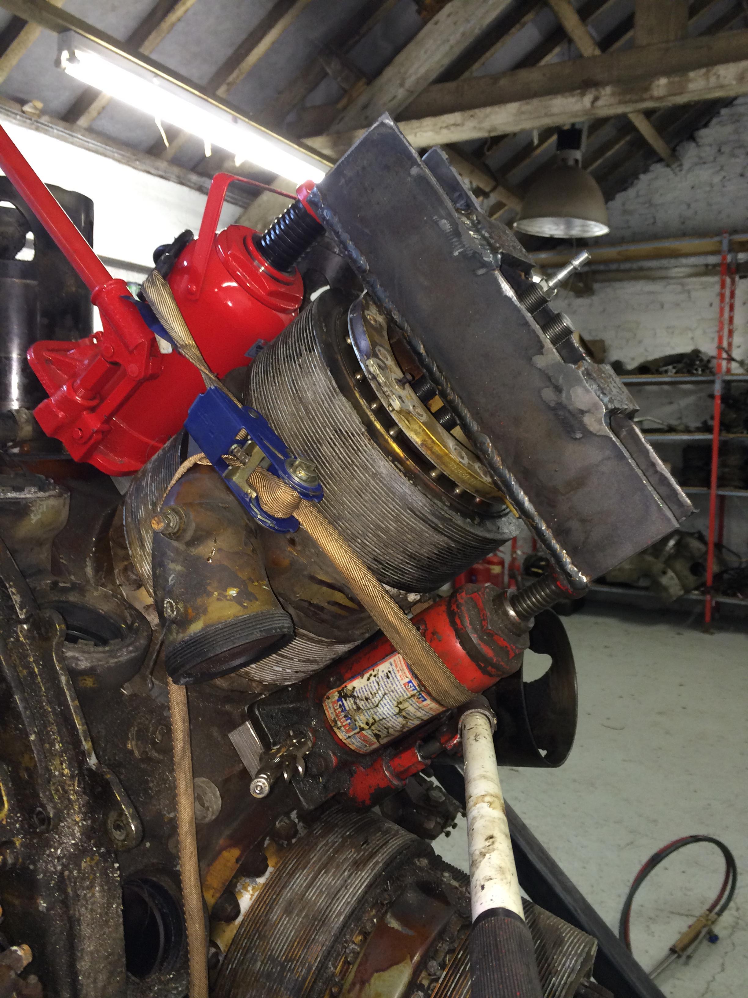
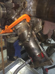
We then welded together some old puller legs to fit around the sleeve, inserted a plate on top of the piston along with the push jack. The hydraulic connection just happened to come out of one of the ports! That was lucky……
We only needed to move the sleeve about 1.5″ down to give us clearance.
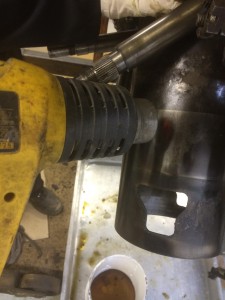
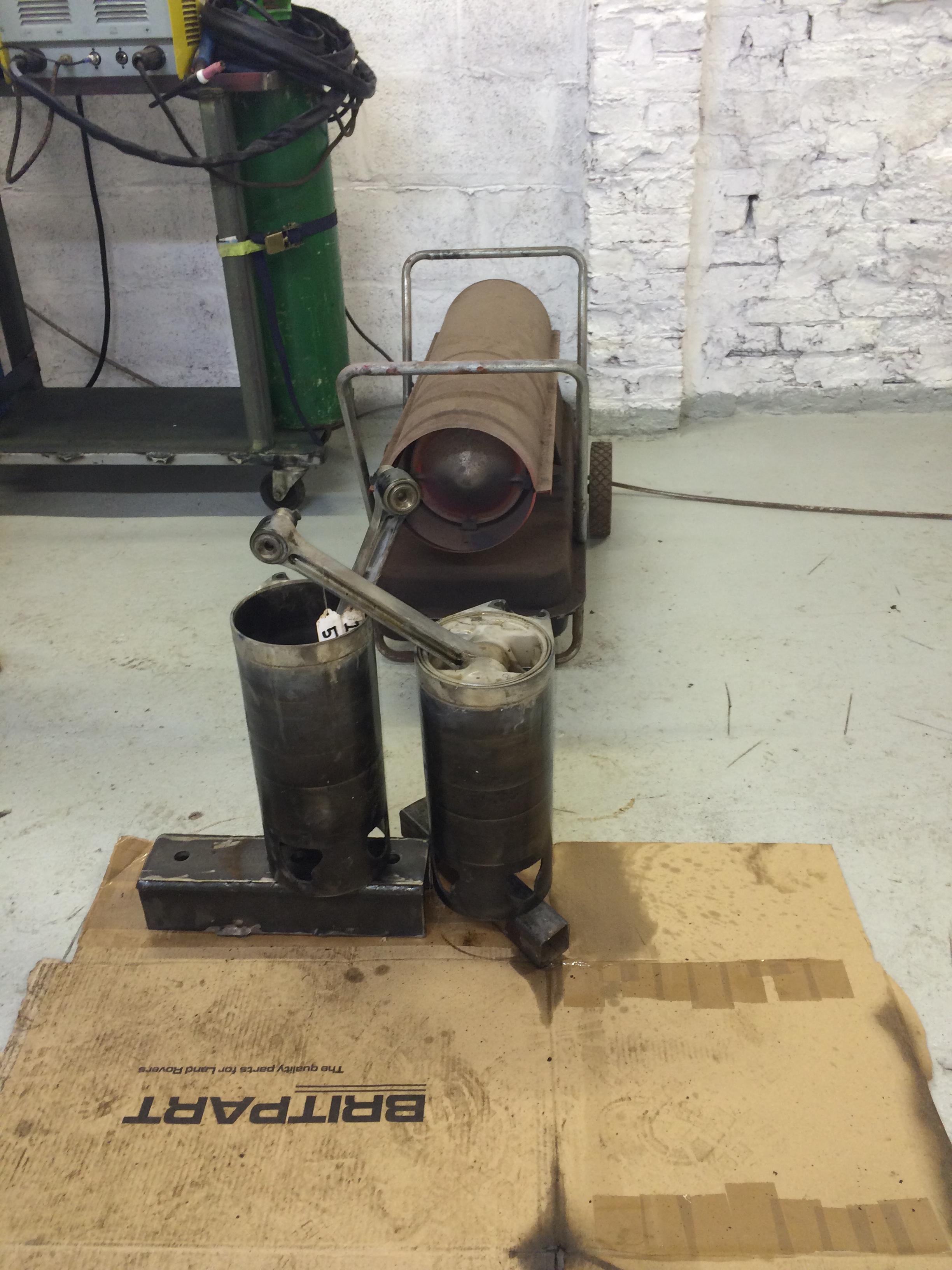
With a bit of gentle heat from a heat gun it soon moved down.


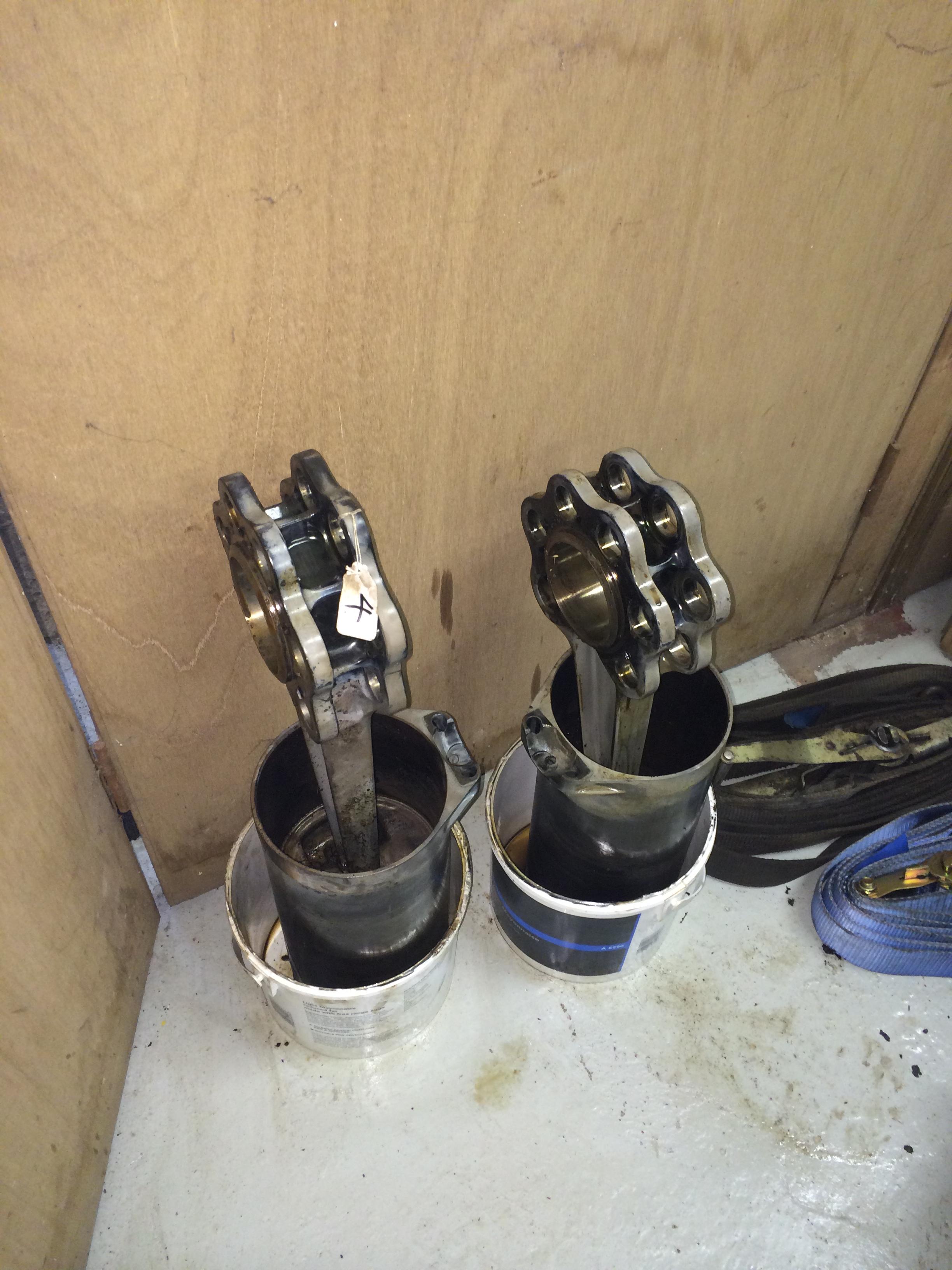
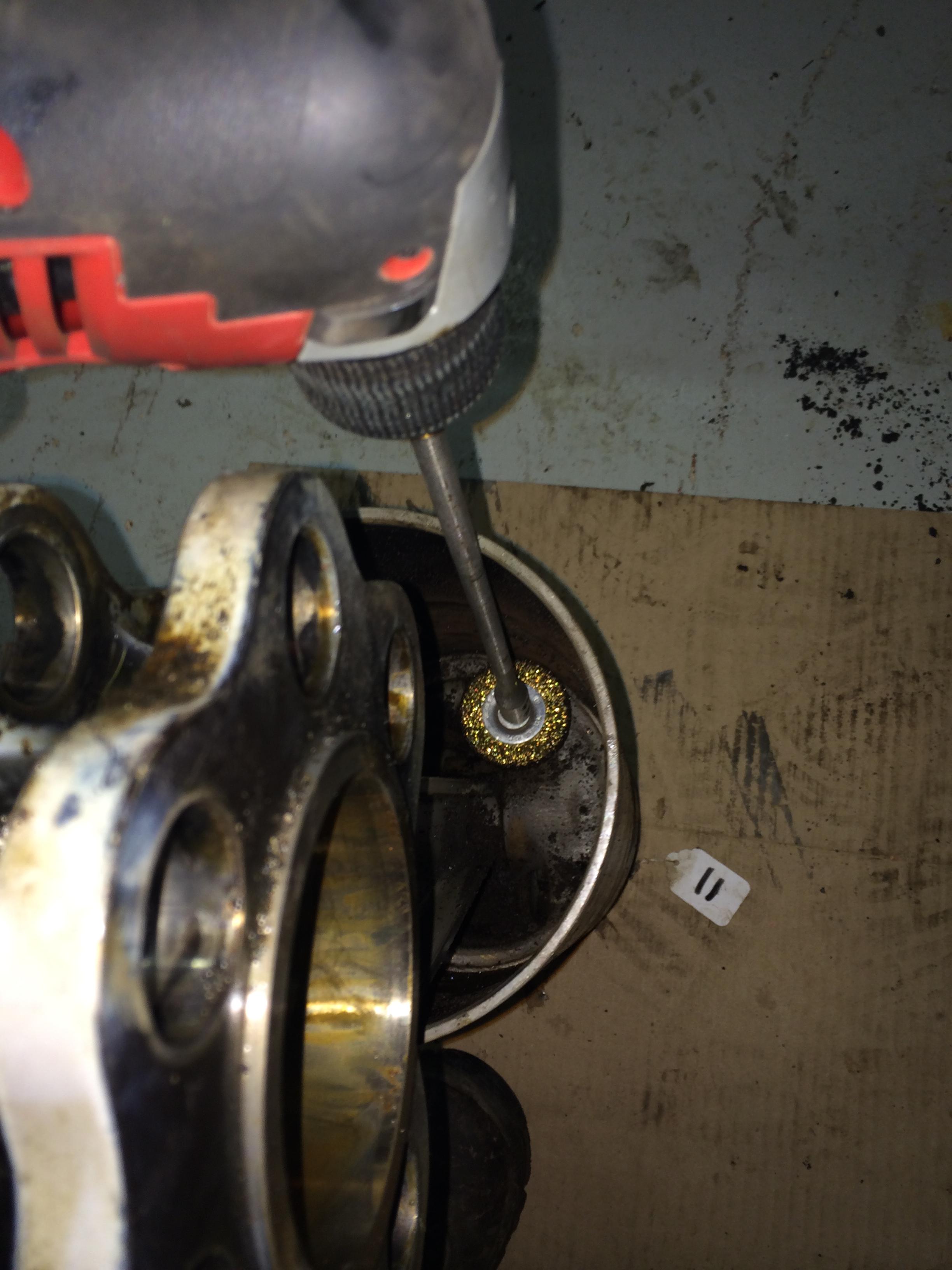
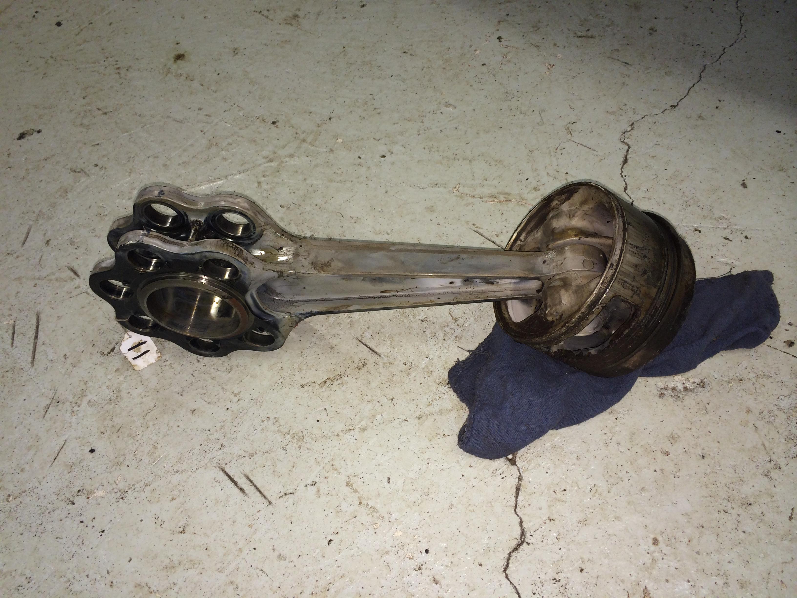
With both maneton bolts removed, it was a fairly straight forward job to remove the front part of the crank. We then removed the front row master con rod and all of the slave rods as one unit, we then removed the circlips on the wrist pins and dismantled it.
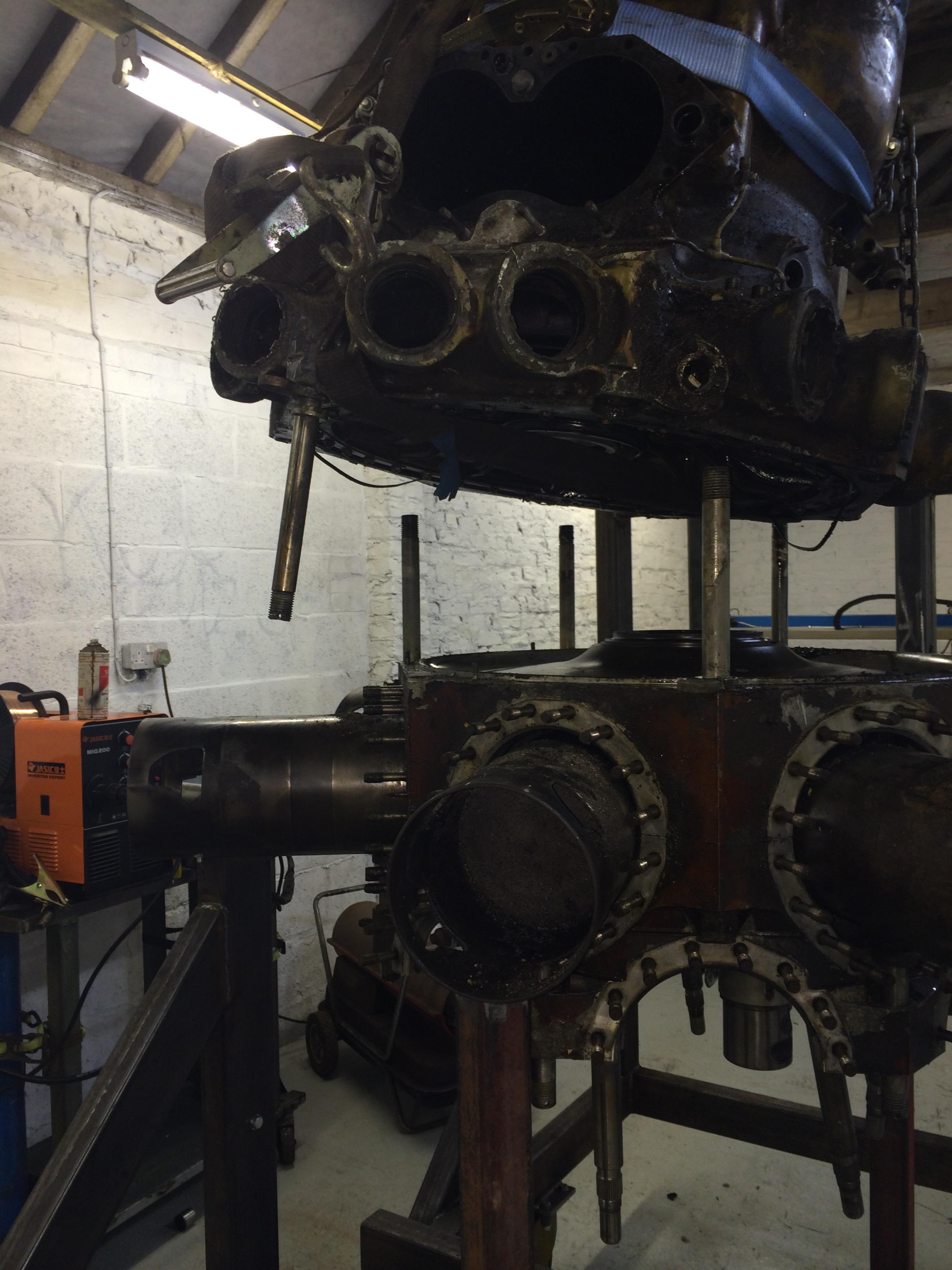
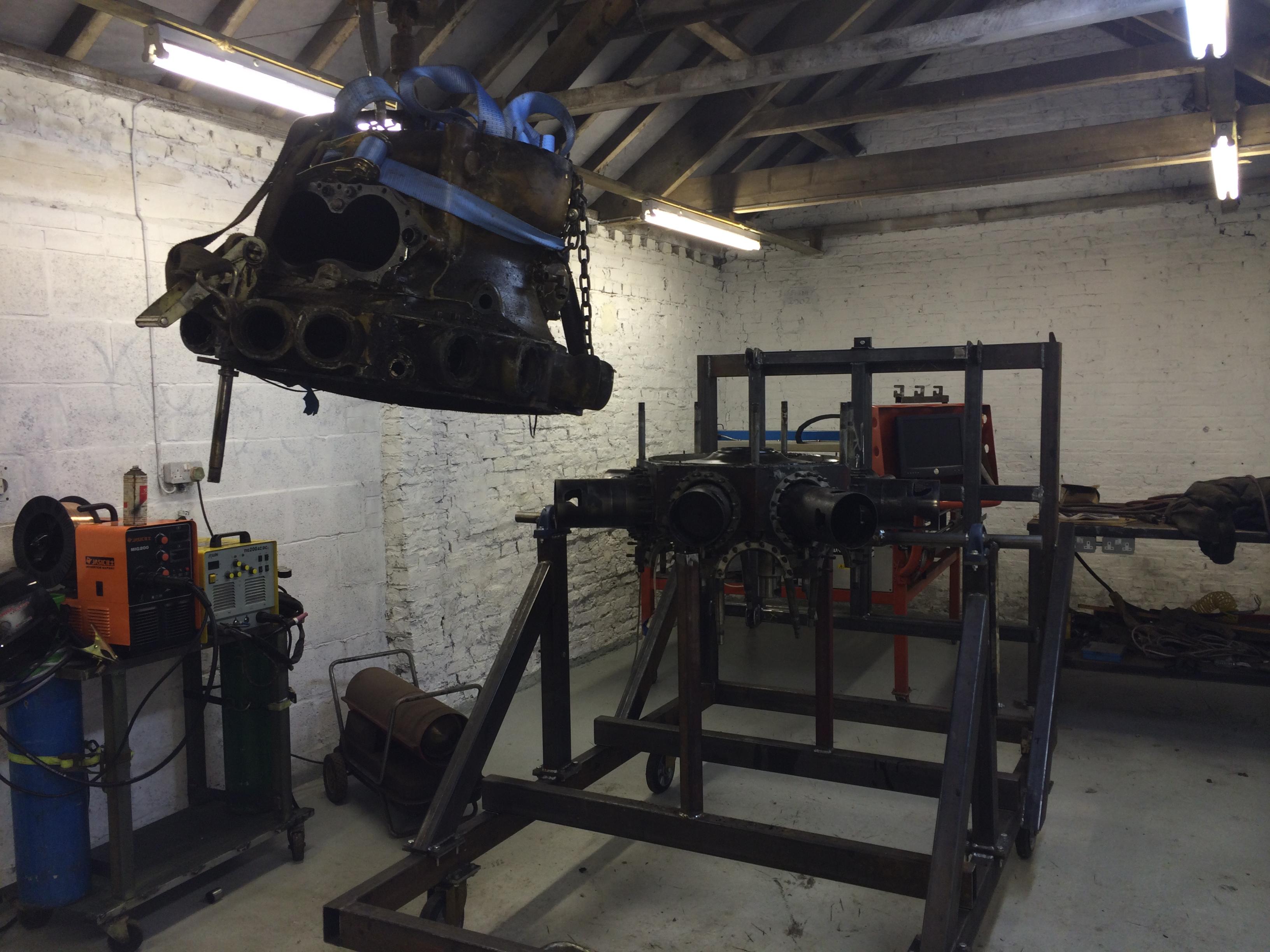
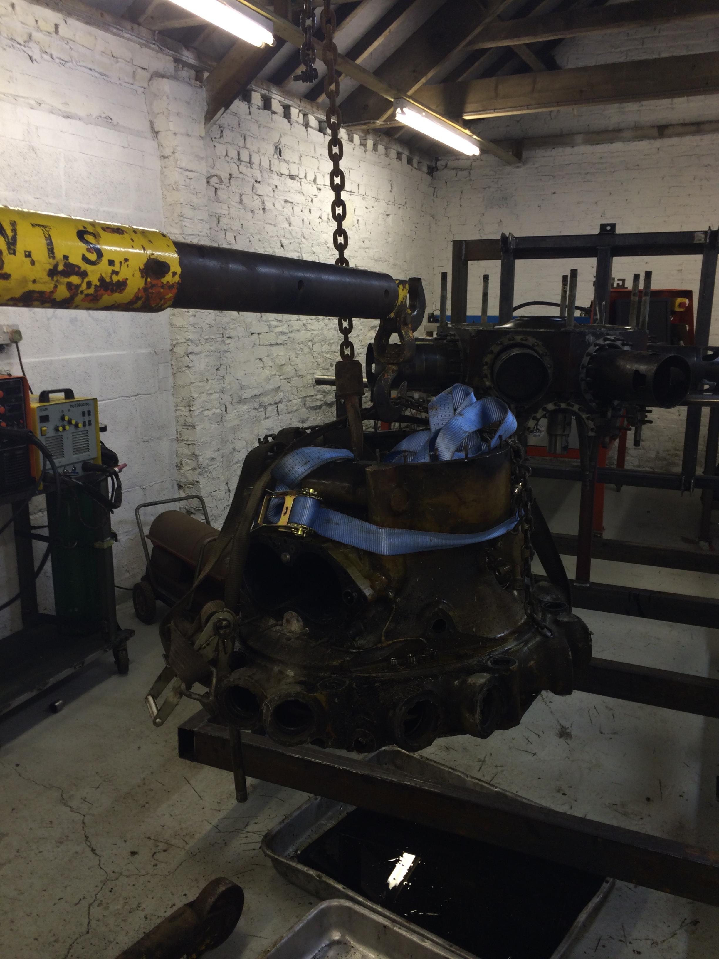
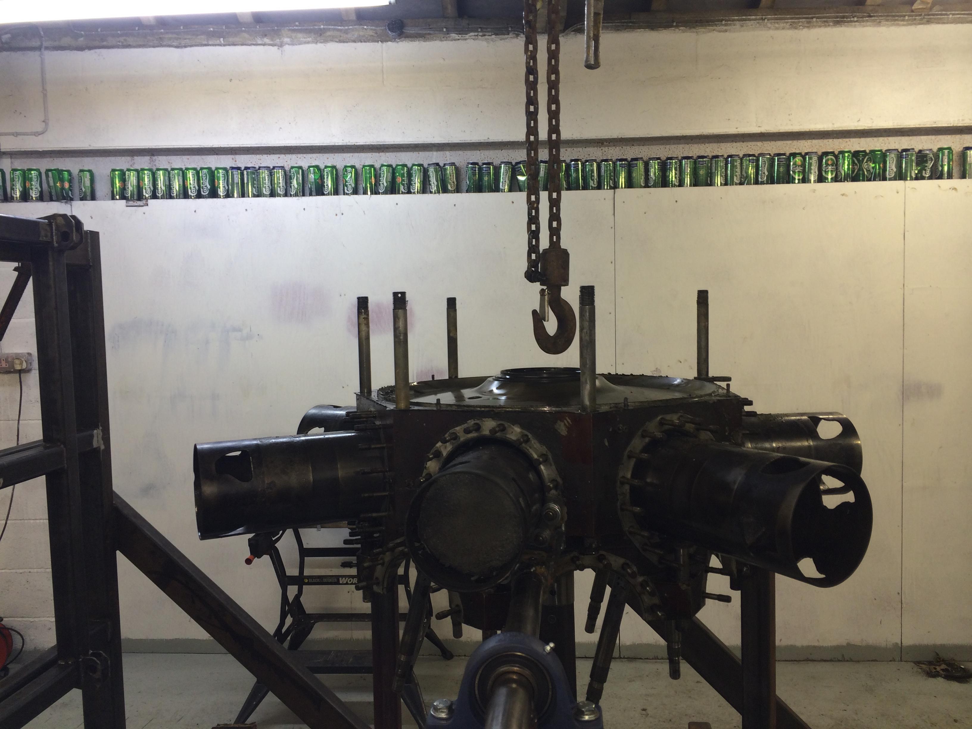
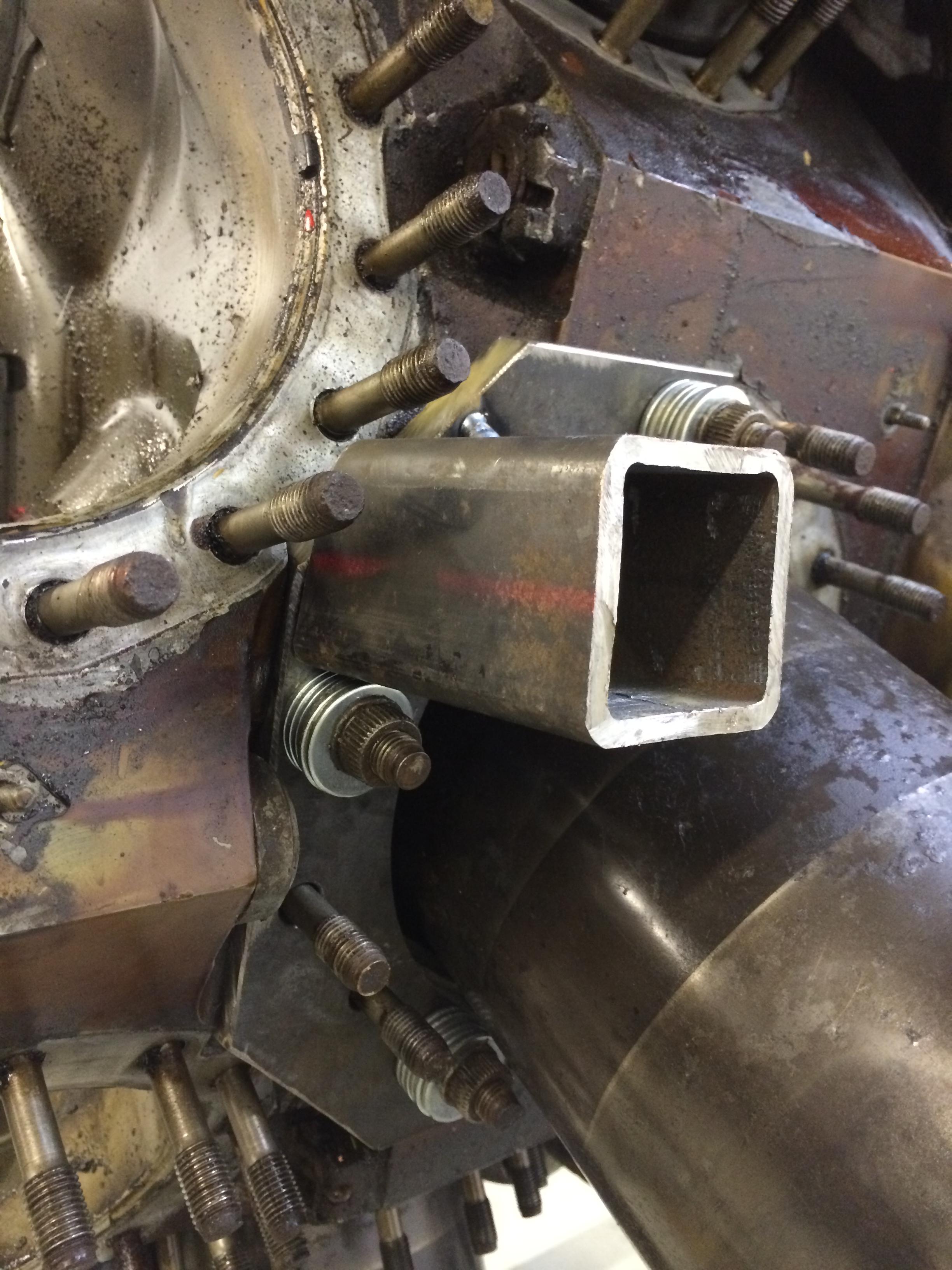
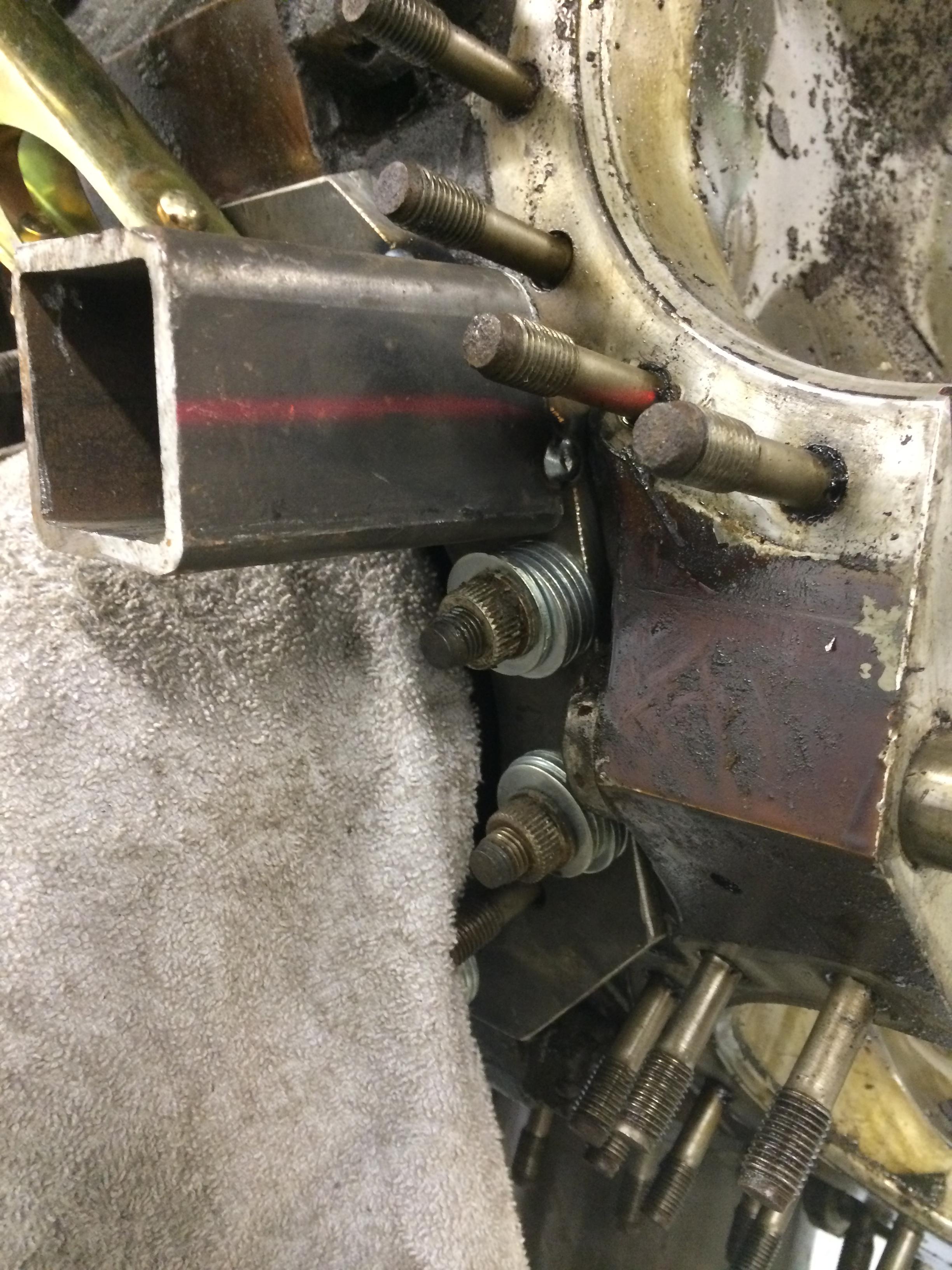
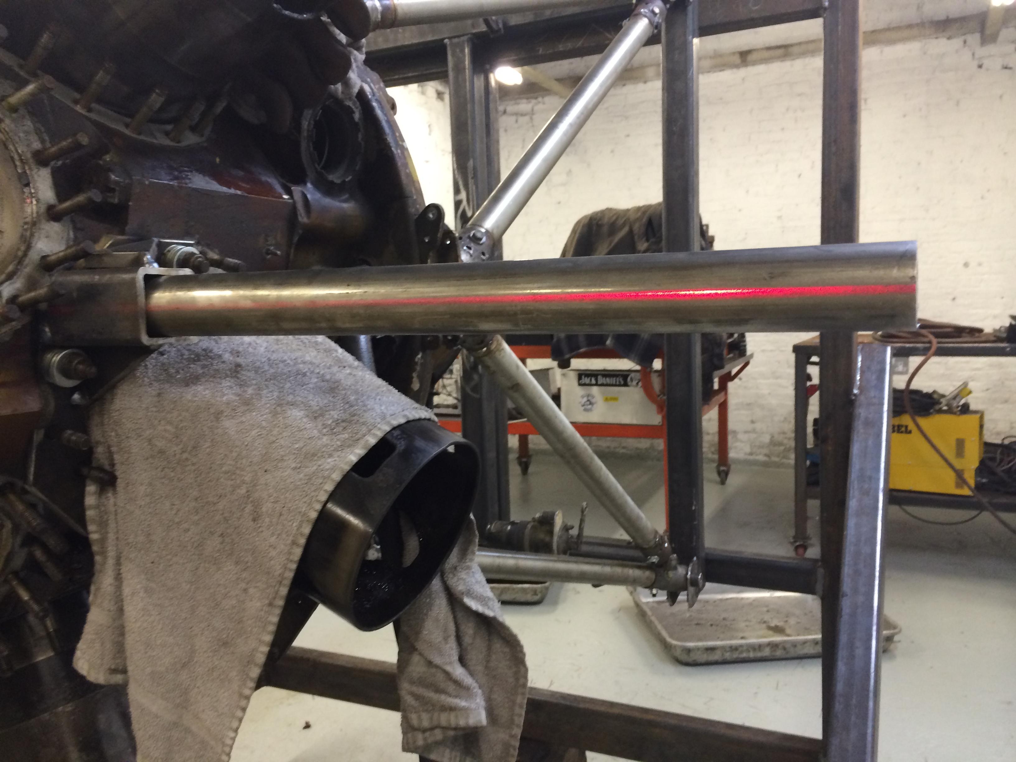
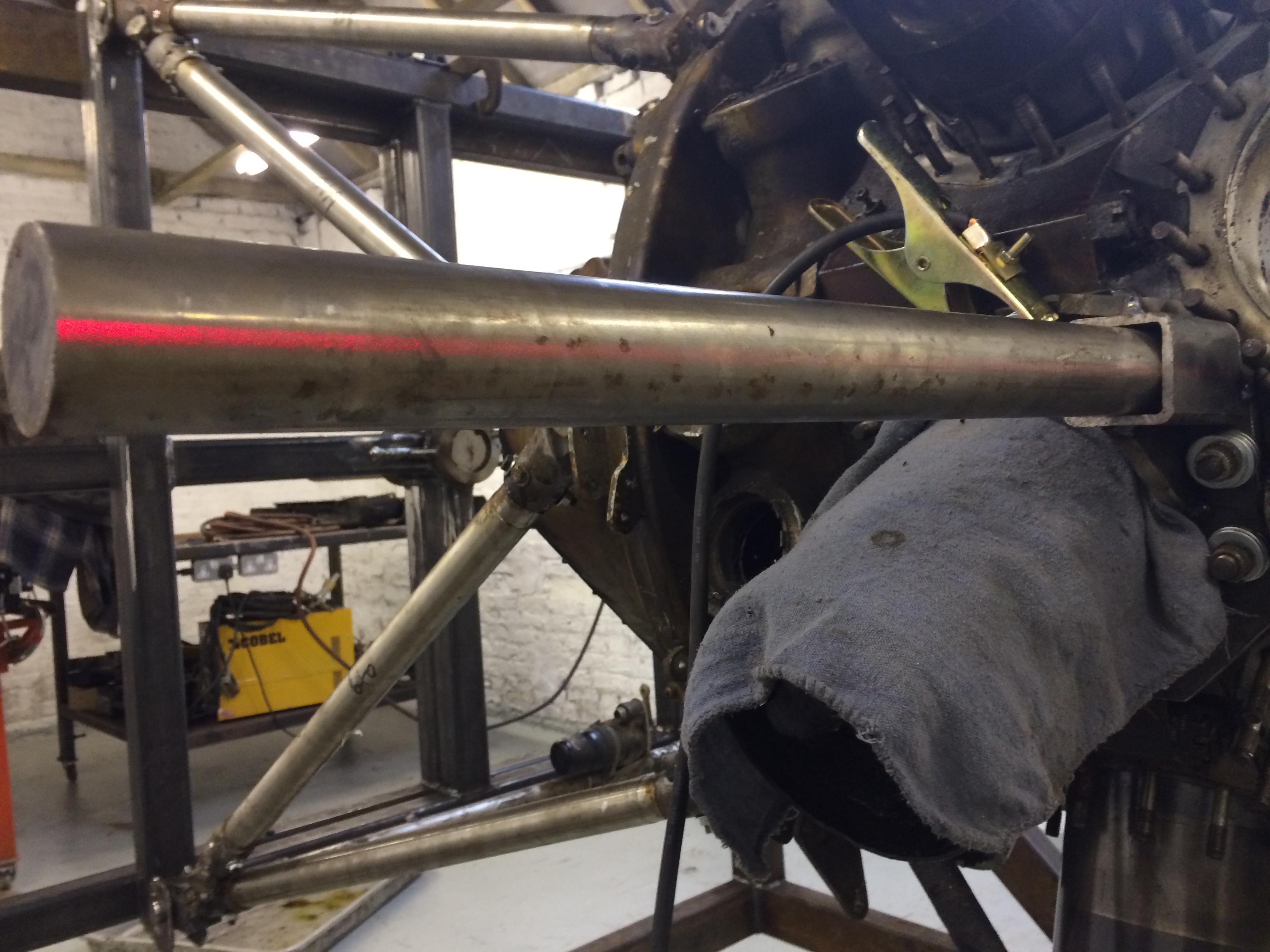
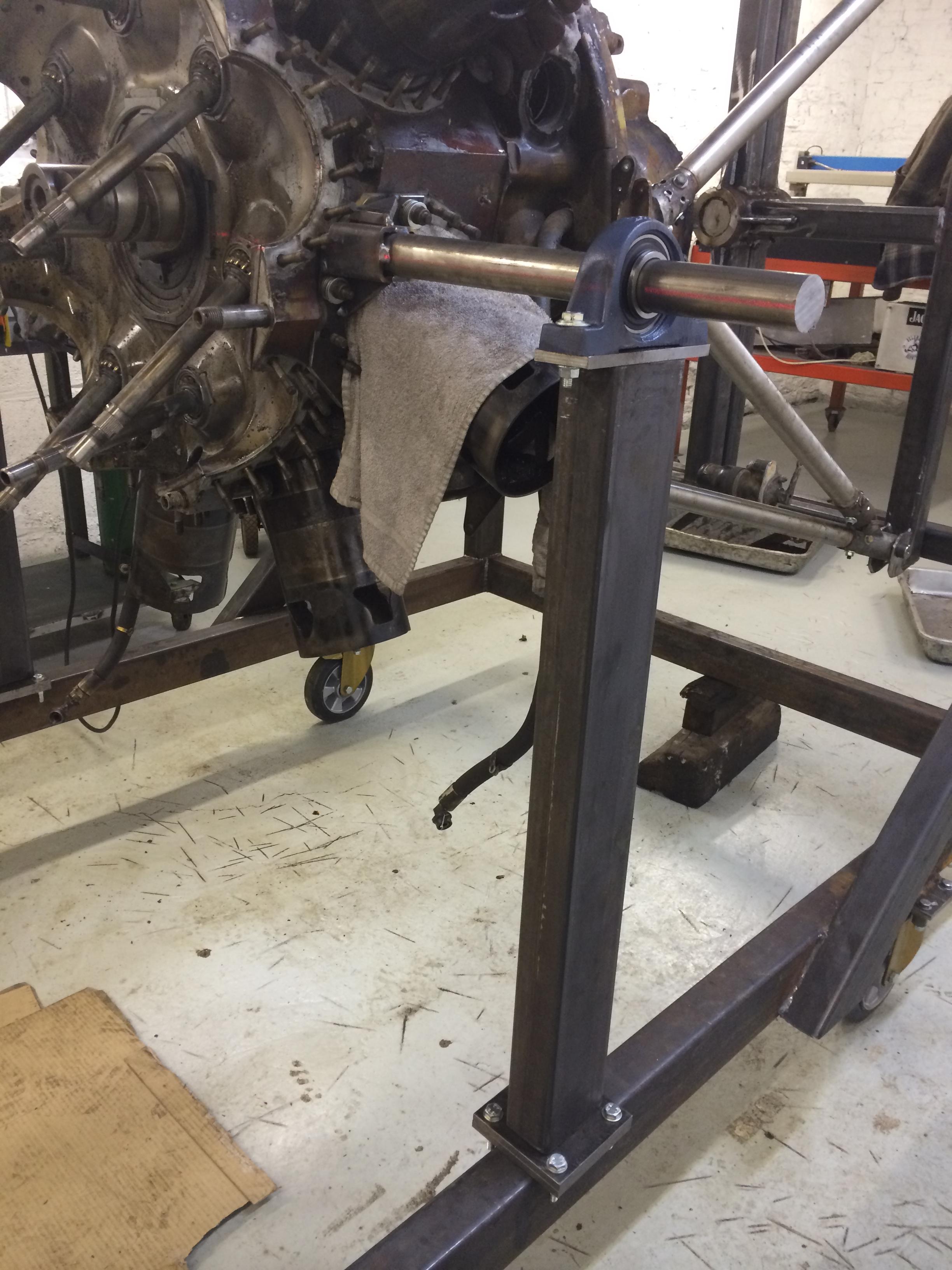
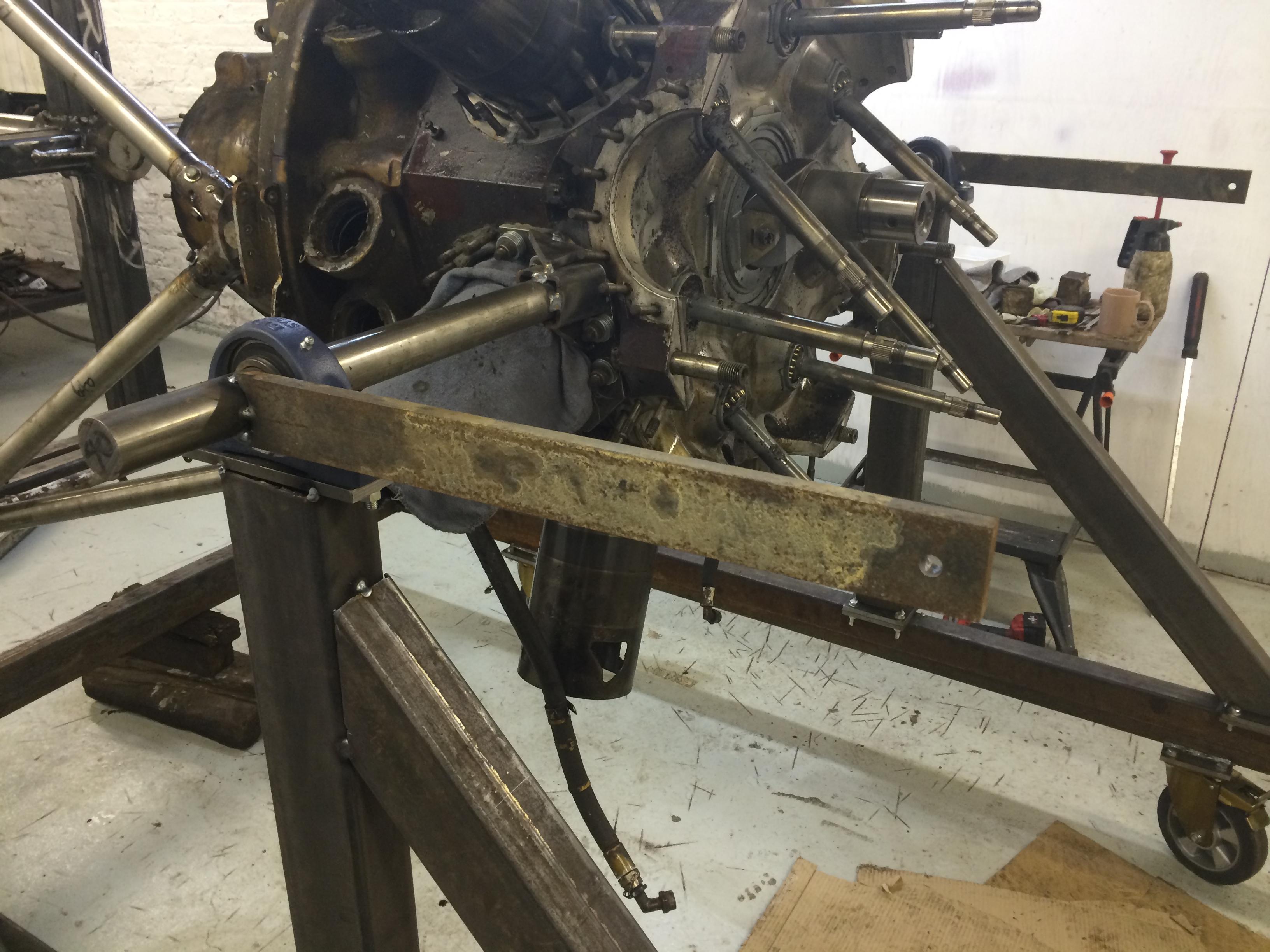
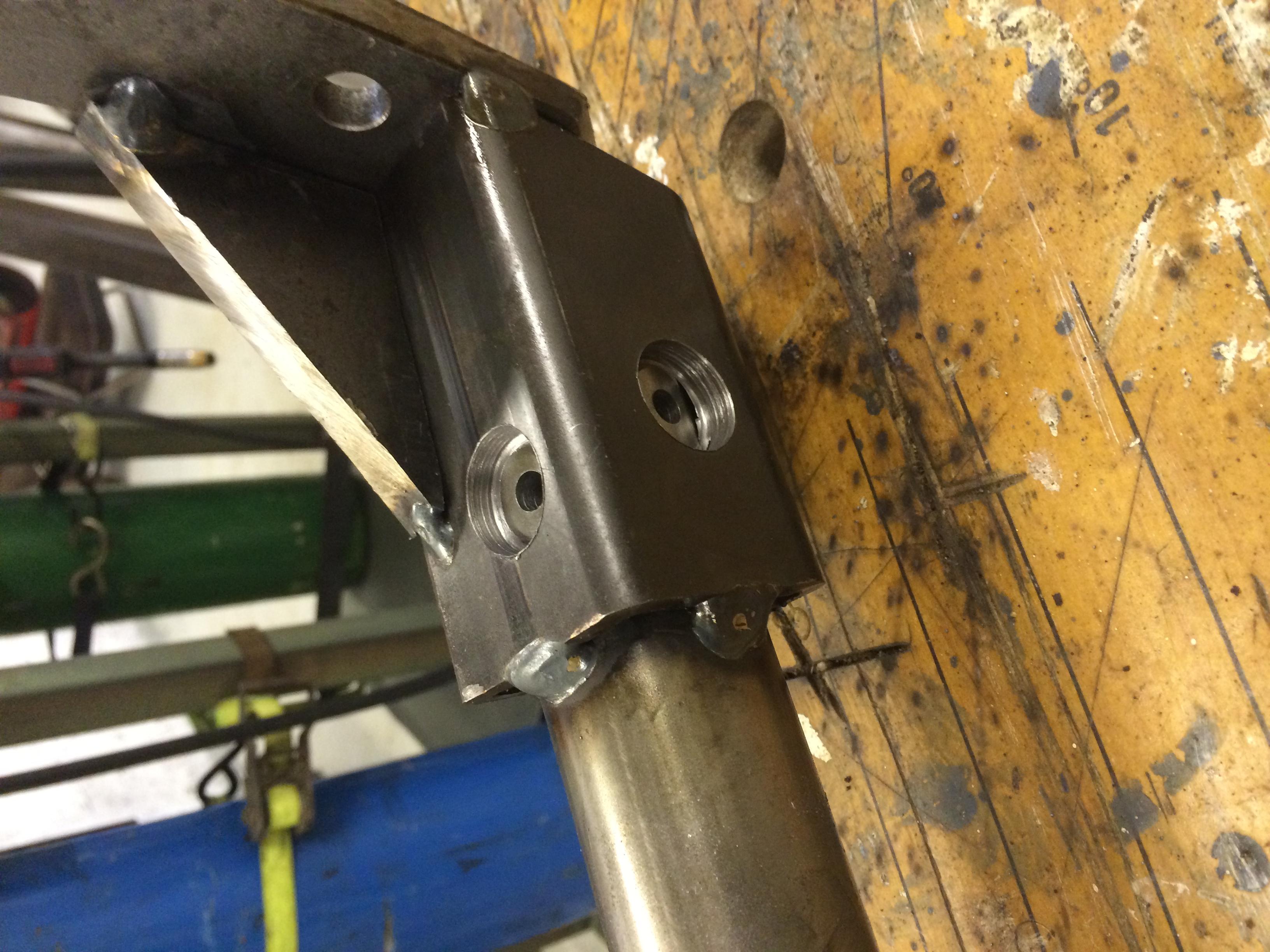
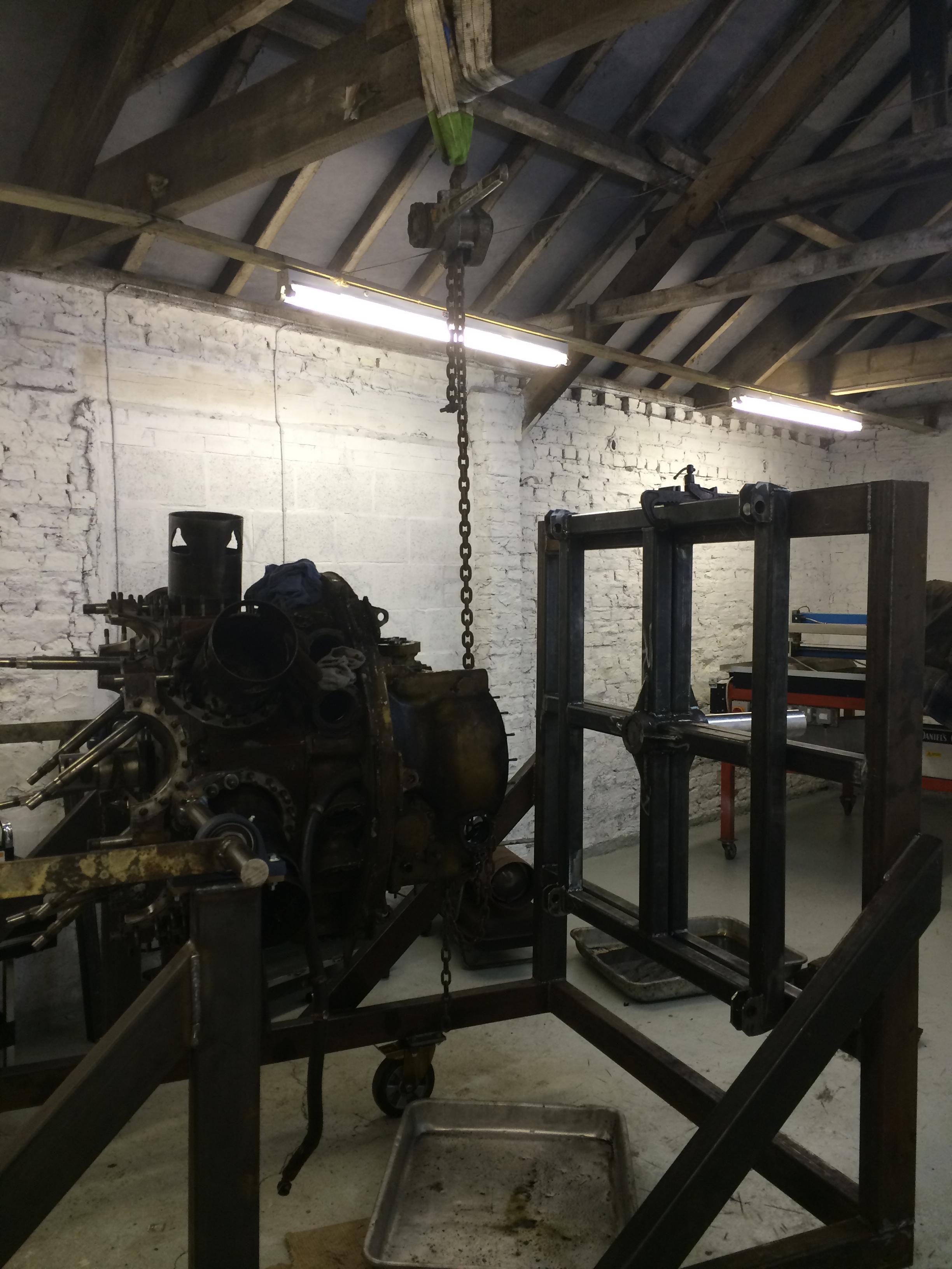
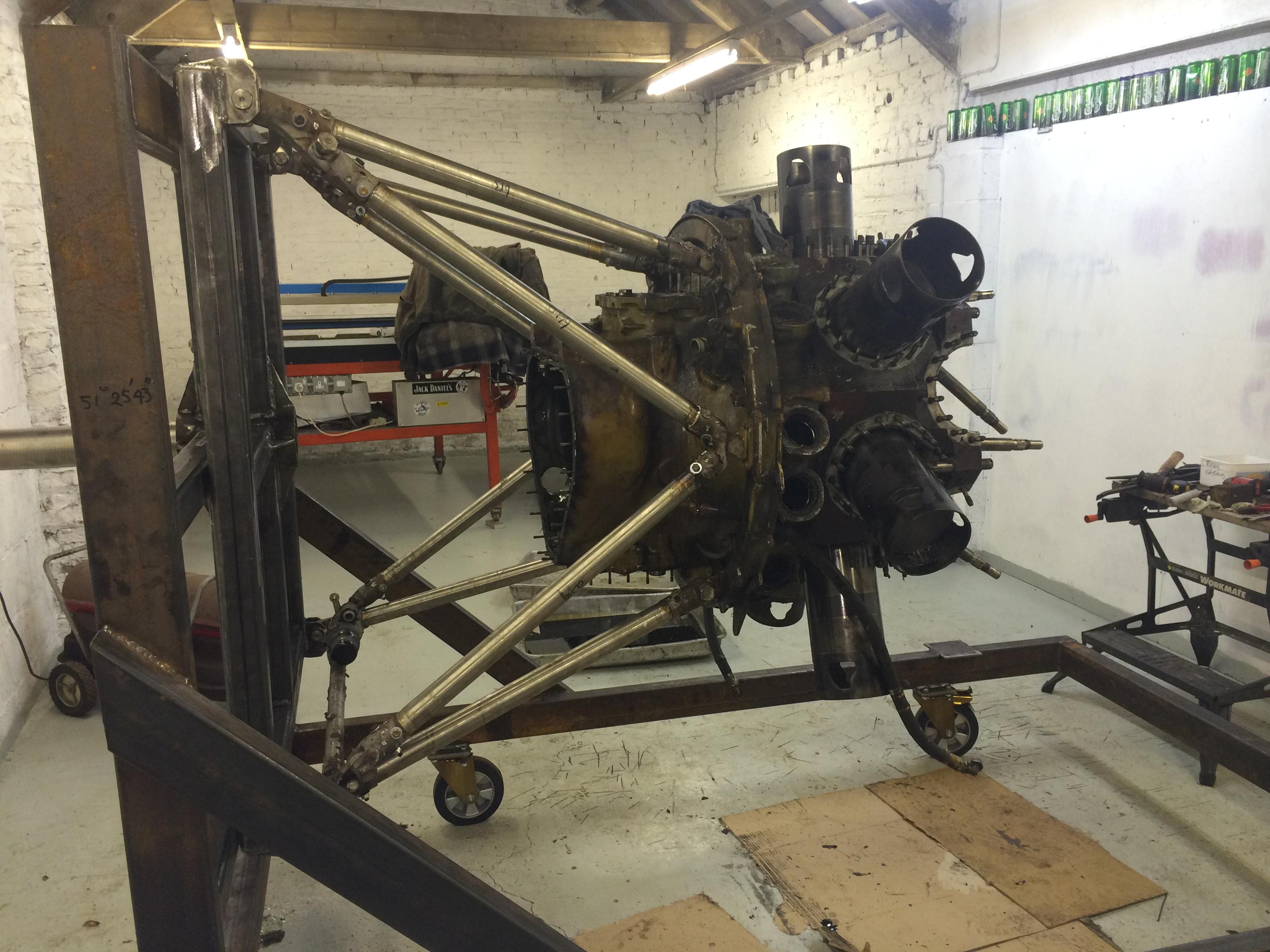
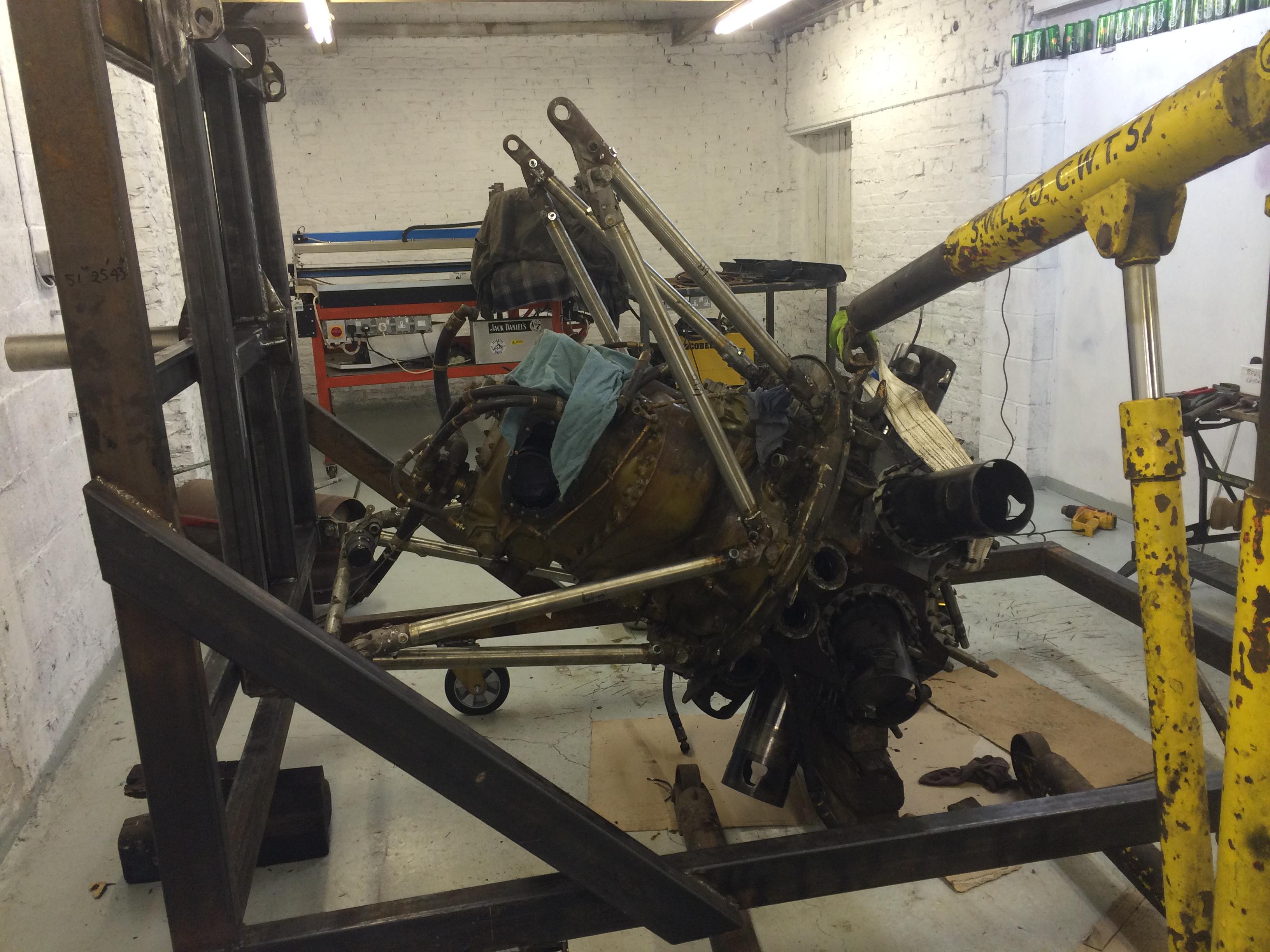
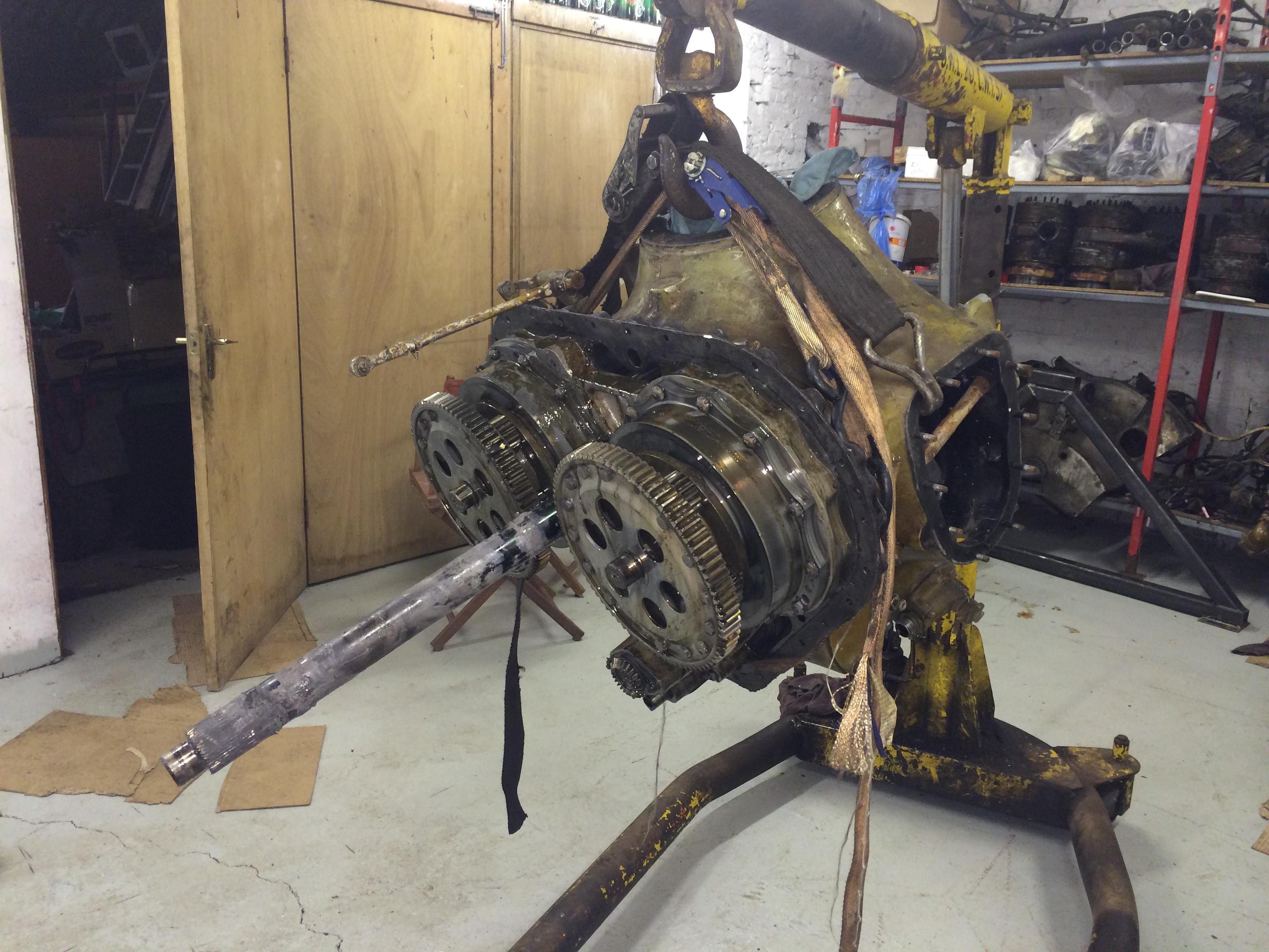
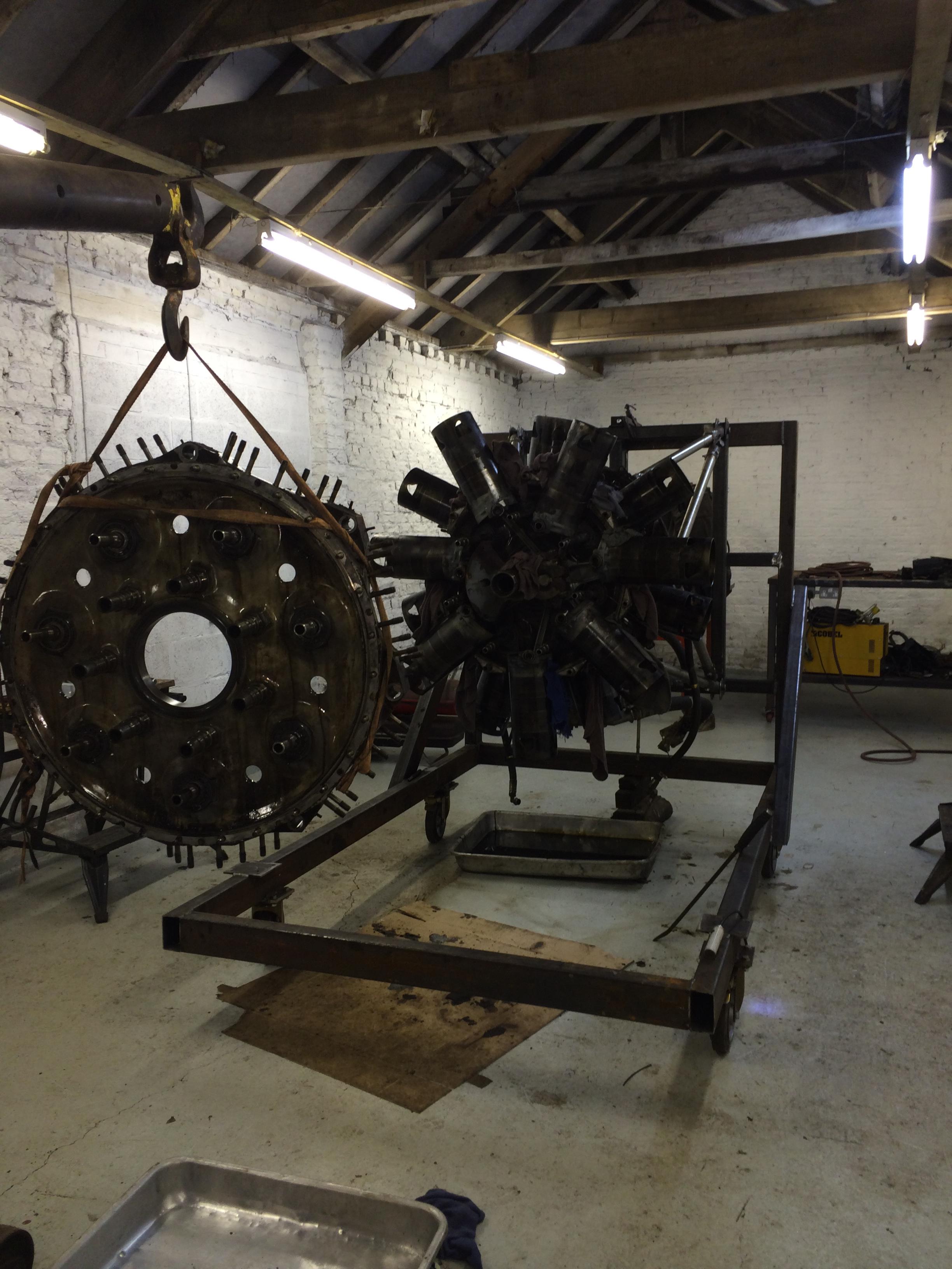
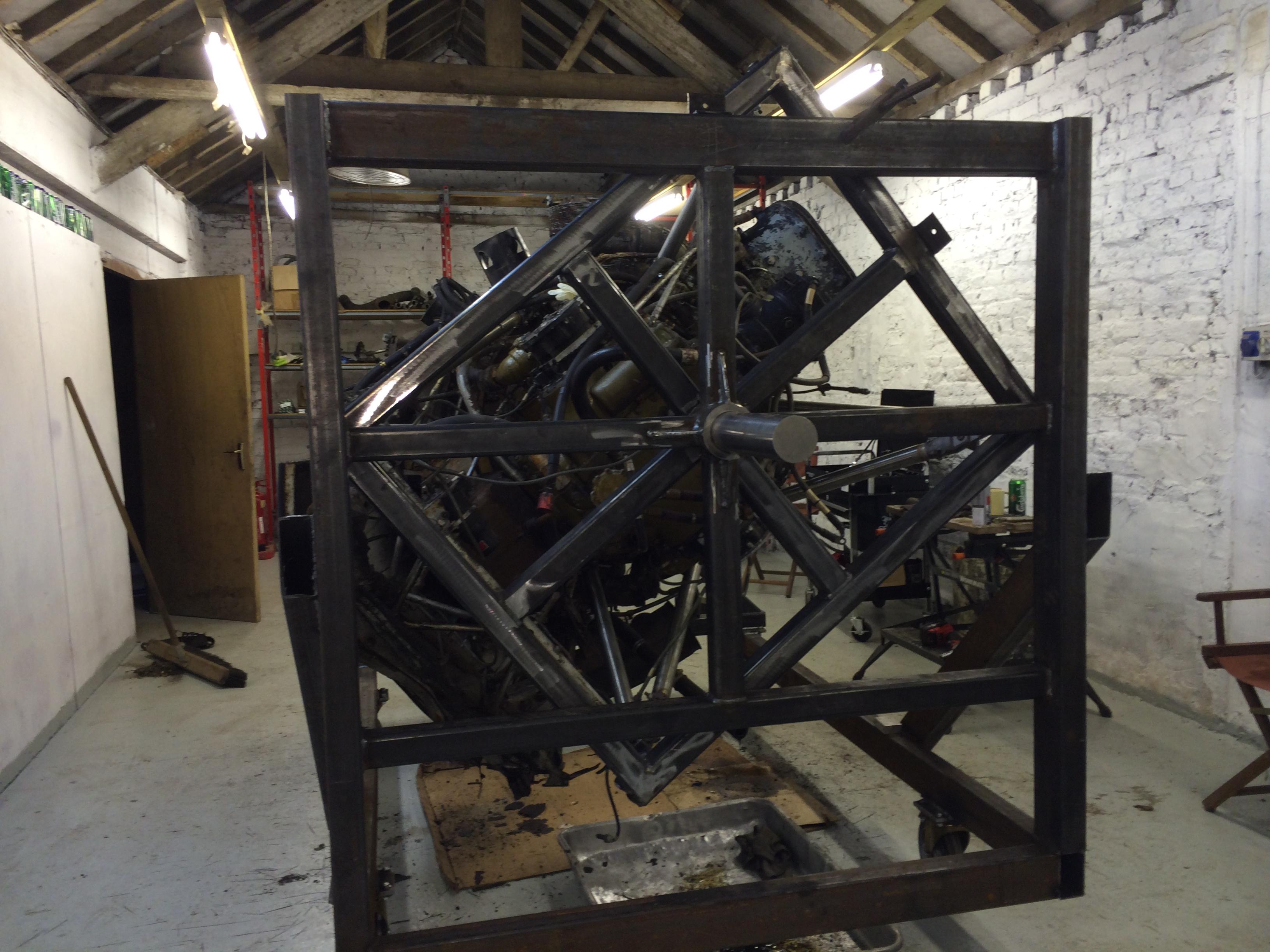
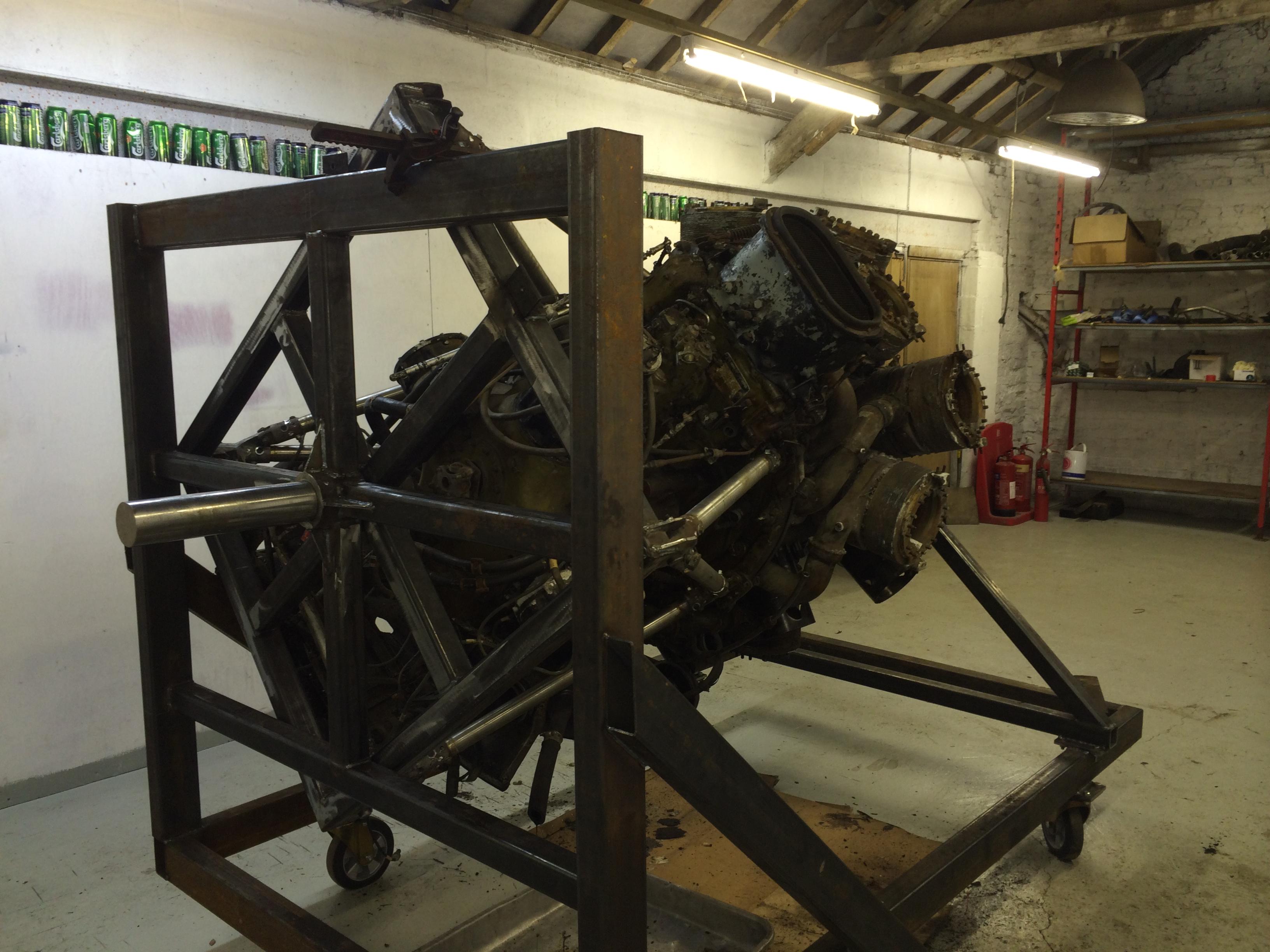
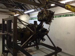
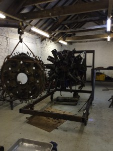
Next job make a crankshaft stand addition to our frame, this will allow us to rotate the engine unto the vertical position, this allow us to strip down the rear section of the engine, gearbox, supercharger and rear set of sleeves etc.