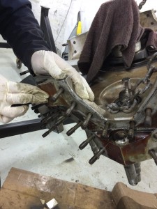
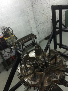
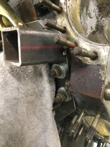
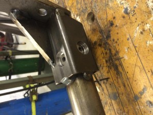
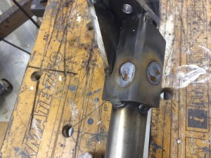
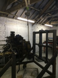
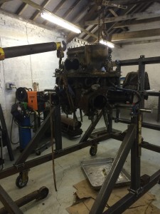
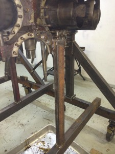
Well we have been busy cleaning the middle crank case section, flattening down the paint so it will be ready for paint when assembled.
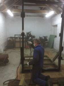
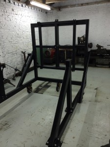
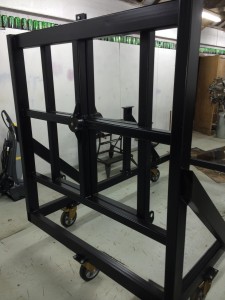
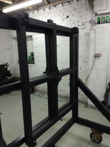
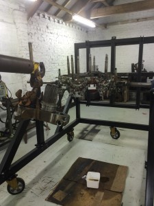
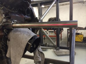
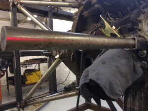
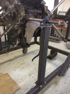
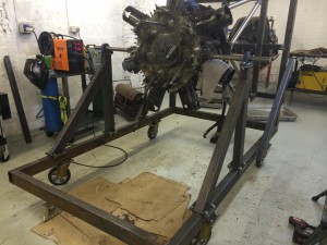
Before we can start putting parts back onto the engine assembly stand, Pete did a great job of prepping the stand then etch prime , then a couple of coats of satin black.
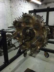
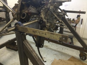
The first section to go back on was the center section.
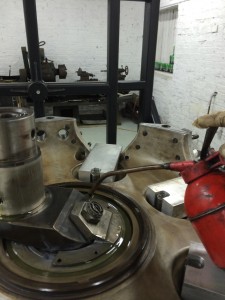
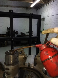
Next after cleaning the crank oil jets they were refitted. We are using 75/90 oil to lubricate all parts as they are fitted.
A good slug of oil fed into main center bearing.
Also plenty of oil down the center of the crank before fitting the end plugs.
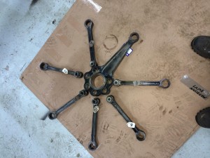
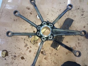
Next after a final wipe down, the front even row master rod and con rods were reassembled ready to be fitted.
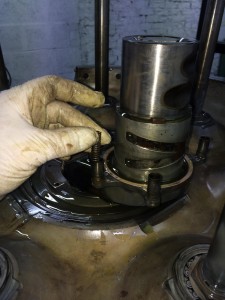
Before the con rods can be fitted the oil feed ring is fitted and lubed up.
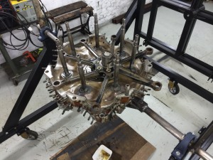
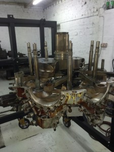
That’s a good mile stone achieved, the even set of con rods fitted, time for a beer!
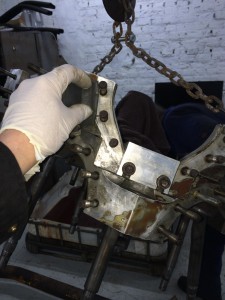
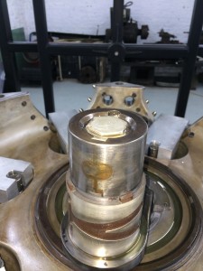
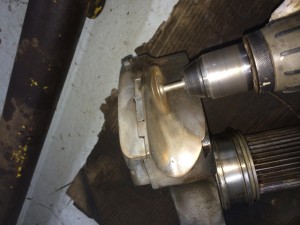
Next job was to clean the front maniton of little patches of surface rust.
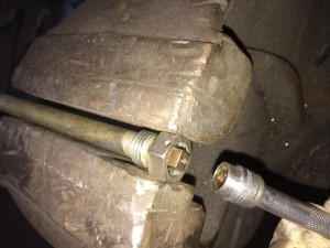
Also we removed the maniton jet and cleaned it out ,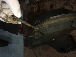
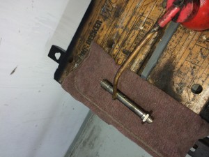
Another little special tool was made from a 1/4″ drive extension to remove the jet.
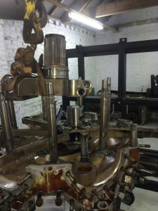
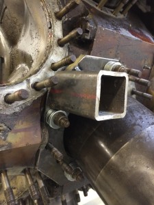
We the aid of our third member of the team Mr. Engine Hoist the front maniton was refitted and lined up.
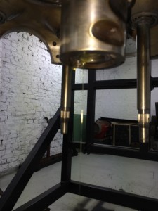
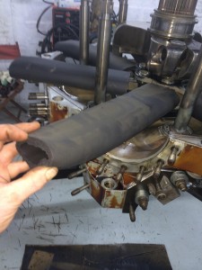
We have fitted pipe insulation to the con rods to protect them while the rest of the assembly is carried out, so when we are turning the engine and the con rods flop about there coating won’t get damaged.
The next job will be to fit and tighten the front maniton stretch bolts, this will have to wait to next weekend, as this will take three people to achieve the tension required!
